
X-ray fluorescence spectrometer and x-ray fluorescence analyzing method

a fluorescence analysis and fluorescence spectrometer technology, applied in the field of x-ray fluorescence spectrometer and x-ray fluorescence analyzing method, can solve the problems of not being able to achieve precise analysis as well, and achieve the effect of simple and accurate analysis

Active Publication Date: 2013-04-25
RIGAKU CORP
View PDF3 Cites 6 Cited by
  • Summary
  • Abstract
  • Description
  • Claims
  • Application Information

AI Technical Summary

Benefits of technology

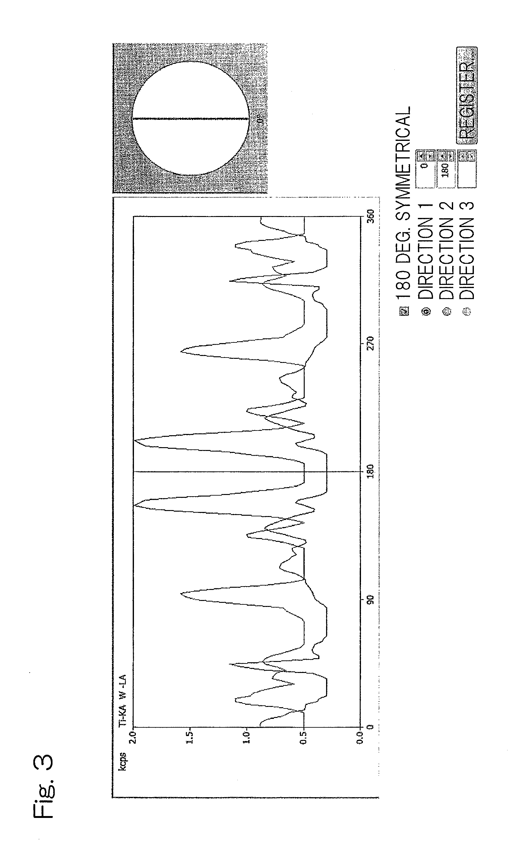
The present invention provides an X-ray fluorescence spectrometer and method that can accurately analyze samples with both crystalline and non-crystalline structures using a compact apparatus that does not require a large space for installation. The apparatus allows for the selection of at least three circumvent angles, which are small angles at which diffracted X-rays can be circumvented. The selected circumvent angle is displayed together with a diffraction profile and / or a measuring surface image of the sample, making it easy for the analyst to determine the position of the selected angle and whether the neighboring intervals are spaced an angle smaller than 180 degrees. Overall, the invention provides a simple and accurate method for analyzing samples using a compact apparatus.

Problems solved by technology

It has, however, been found that in this known method, two directions such as the angle of rotation of the sample, at which the intensity of the secondary X-rays attains the minimum value, and the angle, that is 180 degrees symmetric relative to that angle, are set and, therefore, any other angle than those two angles of rotation cannot be set.
Also, as the circumvent angle for circumventing diffracted X-rays, the angle at which the intensity of the secondary X-rays attains the minimum value is not necessarily the optimum angle and, therefore, no precise analysis can be accomplished as well.
However, it has been found that a diffraction profile, detected actually by the spectrometer, and a diffraction profile theoretically calculated do not necessarily coincide with each other and, hence, no precise analysis can be accomplished.

Method used


Image

  • X-ray fluorescence spectrometer and x-ray fluorescence analyzing method
  • X-ray fluorescence spectrometer and x-ray fluorescence analyzing method
  • X-ray fluorescence spectrometer and x-ray fluorescence analyzing method

Examples


Embodiment Construction

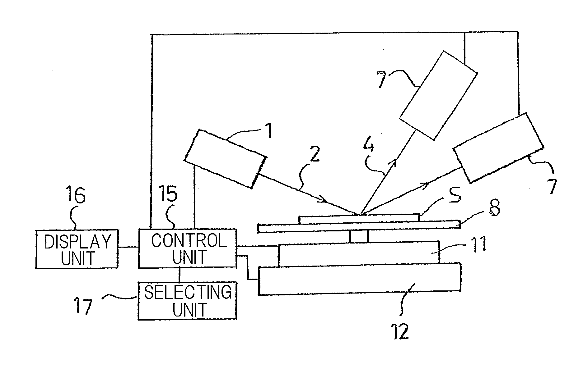
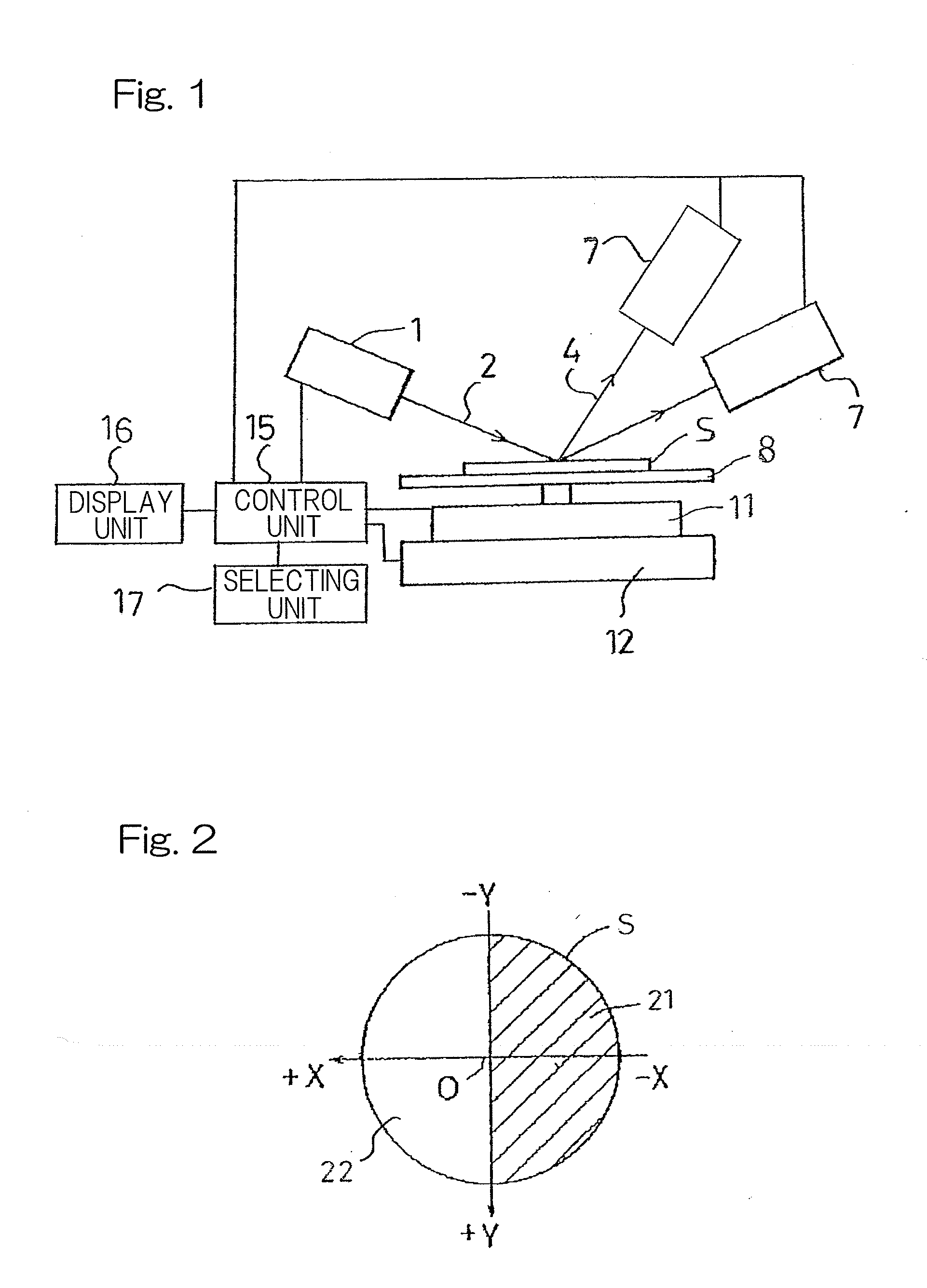
[0032]Hereinafter, an X-ray fluorescence spectrometer according to a preferred embodiment of the present invention will be described in detail. In the first place, the structure of the X-ray fluorescence spectrometer will be described with particular reference to the accompanying drawings. As best shown in FIG. 1, the X-ray fluorescence spectrometer includes an X-ray source 1 such as, for example, an X-ray tube for emitting primary X-rays 2 towards a sample S such as, for example, a monitor wafer, a detecting unit 7 for monochromating secondary X-rays 4, containing fluorescent X-rays and diffracted X-rays, both emitted from the sample S when the latter are irradiated with the primary X-rays 2, by means of a spectroscopic device such as, for example, LiF analyzing crystal and then detecting the intensity of the secondary X-rays 4, a sample table 8 on which the sample is placed, a rotating unit 11 for rotating the sample table 8 about an axis perpendicular to a measuring surface of th...


PUM


Abstract

The X-ray fluorescence spectrometer of the present invention includes a sample table (8) for a sample (S) having a crystalline structure, an X-ray source (1), a detecting unit (7) for detecting secondary X-rays (4) from the sample (S), a rotating unit (11) for rotating the sample table (8), a parallel translating unit (12) for causing the sample table (8) to undergo a parallel translational movement, a selecting unit (17) for selecting three of circumvent angles, at which diffracted X-rays can be circumvented, based on a diffraction profile obtained from the angle of rotation of the sample (S) and the intensity of secondary X-rays (4), the interval between the neighboring circumvent angles being smaller than 180°, and a control unit (15) for controlling the rotating unit (11) so as to set the sample (S) at the circumvent angle at which the sample table (8) will not interfere with any other structures.

Description

CROSS REFERENCE TO THE RELATED APPLICATION[0001]This application is based on and claims Convention priority to Japanese patent application No. 2010-151828, filed Jul. 2, 2010, the entire disclosure of which is herein incorporated by reference as a part of this application.BACKGROUND OF THE INVENTION[0002]1. Field of the Invention[0003]The present invention relates to an apparatus and a method both capable of accomplishing an accurate analysis, by minimizing an intensity of the diffracted X-rays incident on the detector, in the practice of the X-ray fluorescence analysis of a sample of a kind having a crystalline structure such as, for example, a monocrystal wafer (including, for example, a monocrystal silicon wafer and a monocrystal gallium arsenide wafer), which is used in the manufacture of semiconductor electronic circuit elements, and a monitor wafer formed by depositing, for example, electrode films over an entire measuring surface of a monocrystal silicon wafer.[0004]2. Descri...

Claims


Application Information

Patent Timeline
IPC IPC(8): G01N23/223
CPCG01N23/223G01N2223/076G01N2223/6116G01N2223/3306
Inventor KITA, HIROAKIKOBAYASHI, HIROSHI
Owner RIGAKU CORP
Learn More