Left-right wheel drive force distribution control apparatus for a vehicle

a control apparatus and left-right wheel technology, applied in the direction of process and machine control, instruments, etc., can solve the problems of excessive transient control of the left-right wheel drive force distribution, unstable vehicle behavior, and large yaw rate, and achieve the effect of degrading the driving experien

Inactive Publication Date: 2013-04-25
NISSAN MOTOR CO LTD
View PDF0 Cites 12 Cited by
  • Summary
  • Abstract
  • Description
  • Claims
  • Application Information

AI Technical Summary

Benefits of technology

[0008]The present invention takes into account the fact that the gain of the vehicle behavior increases when the steering speed is high and its object is to provide a vehicle left-right wheel drive force control device that can solve the previously explained problem of degraded drivability by weakening the transient control of the left-right wheel drive force distribution when the steering speed is high such that an unnecessarily large yaw rate does not occur when the steering speed is high and, thus, the vehicle behavior is stabilized.
[0013]However, with the present invention, when the direction change operation speed is fast, the transient control amount of the left-right drive force difference calculated based on the transient turning response request of the driver is revised to a decreased value before being contributed to the left-right wheel drive force control. Thus, an unnecessarily large yaw rate will not occur when the direction change operation speed is fast. As a result, the problem of the vehicle behavior becoming unstable and the drivability degrading can be solved.

Problems solved by technology

Consequently, when the steering speed is high such that the gain of the vehicle behavior (yaw rate) with respect to the steering speed is high, the transient control of the left-right wheel drive force distribution becomes excessive and the yaw rate becomes larger than necessary.
As a result, the vehicle behavior becomes unstable and the drivability degrades.
If the left-right drive force difference transient control amount calculated based on the transient turning response request of the driver is used as is in the left-right wheel drive force distribution control, then the behavior gain of the vehicle will be high when the direction change operation speed is fast and the transient control amount of the left-right wheel drive force distribution will become excessively large.
Consequently, the behavior of the vehicle will become unstable and the drivability will degrade.

Method used


Image

  • Left-right wheel drive force distribution control apparatus for a vehicle
  • Left-right wheel drive force distribution control apparatus for a vehicle
  • Left-right wheel drive force distribution control apparatus for a vehicle

Examples


Embodiment Construction

[0021]Embodiments of the present invention are described in detail below with reference to the embodiments in the drawings.

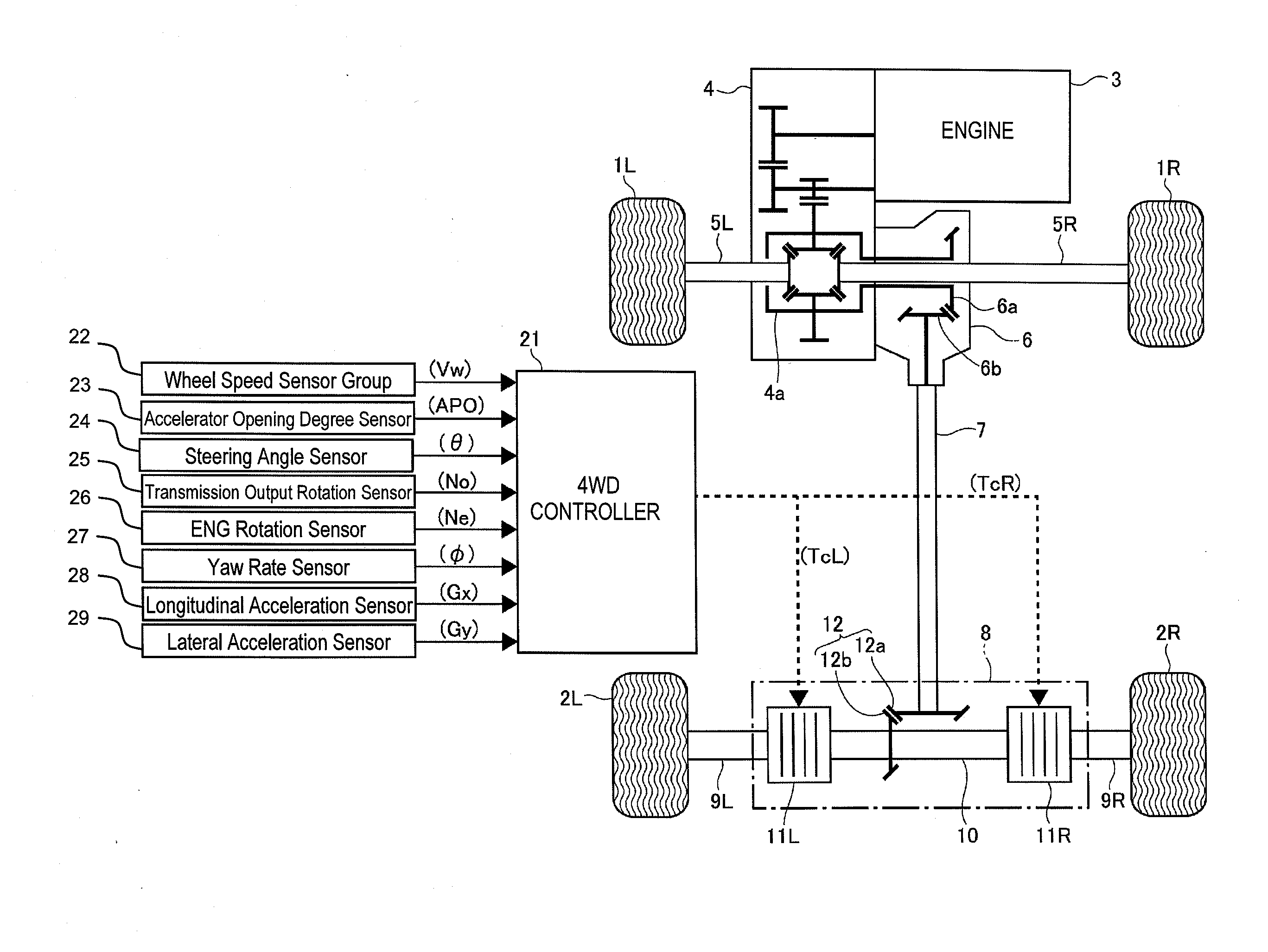
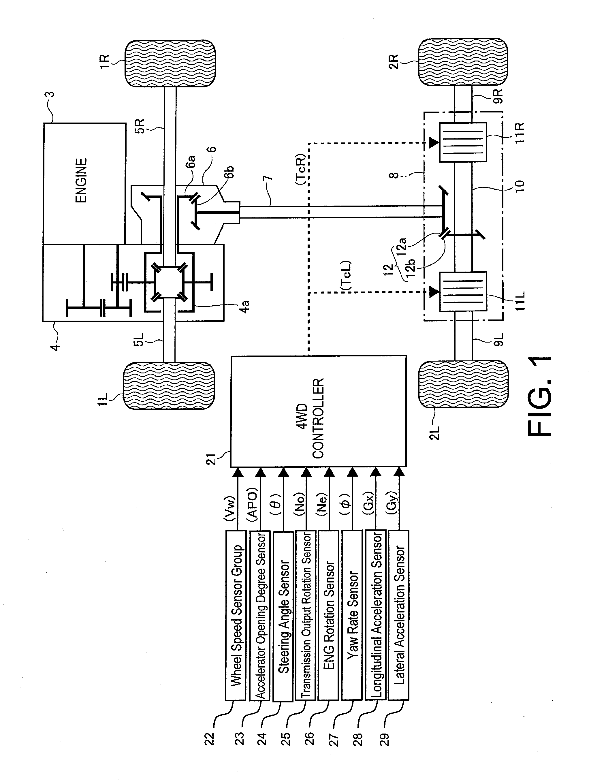
[0022]FIG. 1 is a schematic plan view showing a wheel drive train of a four-wheel drive vehicle equipped with a left-right wheel drive force distribution control apparatus according to an embodiment of the present invention as viewed from above the vehicle. A four-wheel drive control system is also shown. The figure shows left and right front wheels 1L and 1R serving as main drive wheels and left and right rear wheels 2L and 2R serving as subordinate drive wheels. In this patent specification, the term “drive force” refers not to power but to a torque value.

[0023]The reference numeral 3 indicates an engine serving as a prime mover. Torque from the engine 3 is multiplied by a transmission 4 (transaxle that includes a differential gear device 4a) and transferred toward the left and right front wheels 1L and 1R through left and right axle shafts 5L and 5R, thereby ...


PUM


Abstract

A calculating section finds a left-right rear wheel drive force difference transient control computation value, which is a basic target value for a turning response transiently requested by a driver through a steering speed at current wheel speeds (vehicle speed). A computing section finds a left-right drive force difference transient control gain based on a target yaw rate change rate such that the control gain is smaller than 1 in a high target yaw rate change rate region. The computing value is multiplied by the control gain to calculate a left-right rear wheel drive force difference transient control amount for a left-right wheel drive force distribution control. As a result, during high-speed steering when the yaw rate gain tends to increase, the left-right drive force difference transient control amount is revised to a decreased value such that the transient control amount causes less of an increase in the yaw rate.

Description

CROSS-REFERENCE TO RELATED APPLICATIONS[0001]This application is a U.S. National stage application of International Application No. PCT / JP2011 / 065394, filed Jul. 5, 2011, which claims priority claims priority under to Japanese Patent Application No. 2010-156661, filed in Japan on Jul. 9, 2010, the entire contents of which is hereby incorporated by reference.BACKGROUND[0002]1. Field of the Invention[0003]The present invention generally relates to a proposal for improving a left-right wheel drive force distribution control apparatus that is useful for a vehicle, particularly a four-wheel drive vehicle.[0004]2. Background Information[0005]Japanese Patent Publication No. 3,116,685 presents an example of a conventional left-right wheel drive force distribution control apparatus for a vehicle. The proposed technology relates to a transient control of a left-right wheel drive force distribution that accomplishes a target behavior change (typically a change of yaw rate) corresponding to a c...

Claims


Application Information

Patent Timeline
Patent Type & Authority Applications(United States)
IPC IPC(8): G06F17/00
CPCB60K17/344B60K23/0808B60W10/16B60W30/045B60W2720/28G06F17/00B60W2720/406F16H48/19F16H2048/204B60K17/3515B60W2720/403
Inventor SUZUKI, SHINICHI
Owner NISSAN MOTOR CO LTD
Why Eureka
Try Eureka