
Acceleration Of A Mass By A Structure Under Central Or Gyration Induced Forces

Active Publication Date: 2013-05-02
WESTMEYER PAUL +1
View PDF7 Cites 3 Cited by
  • Summary
  • Abstract
  • Description
  • Claims
  • Application Information

AI Technical Summary

Benefits of technology

The present invention relates to a method and apparatus for accelerating a mass using gyration induced acceleration. The invention includes a pathway modification to adjust the phase relationship between the mass and the machinery accelerating the mass through the use of delay loops and discontinuities. The invention also includes the use of active controls for dynamic envelope management, which can reduce mechanical interferences and accommodate uncertainties. Shaped traps can also be used to prevent the media from exiting the structures until the end of the pathway. The technical effects of the invention include smaller overall packaging, decrease in overall system power required, and less system mass for the same mass performance compared to previous art.

Problems solved by technology

Other gyration systems use a fixed pathway length, a fixed radius of gyration, or fixed gyration frequency, or the combination, resulting in a limited range of performance and highly restrictive initial conditions for phase stabilized acceleration.

Method used


Image

  • Acceleration Of A Mass By A Structure Under Central Or Gyration Induced Forces
  • Acceleration Of A Mass By A Structure Under Central Or Gyration Induced Forces
  • Acceleration Of A Mass By A Structure Under Central Or Gyration Induced Forces

Examples


Embodiment Construction

[0061]Three families of preferred embodiment exist, one family is based upon just delay lengths (loops), a second family is based upon discontinuities (gaps), and a third has both features.

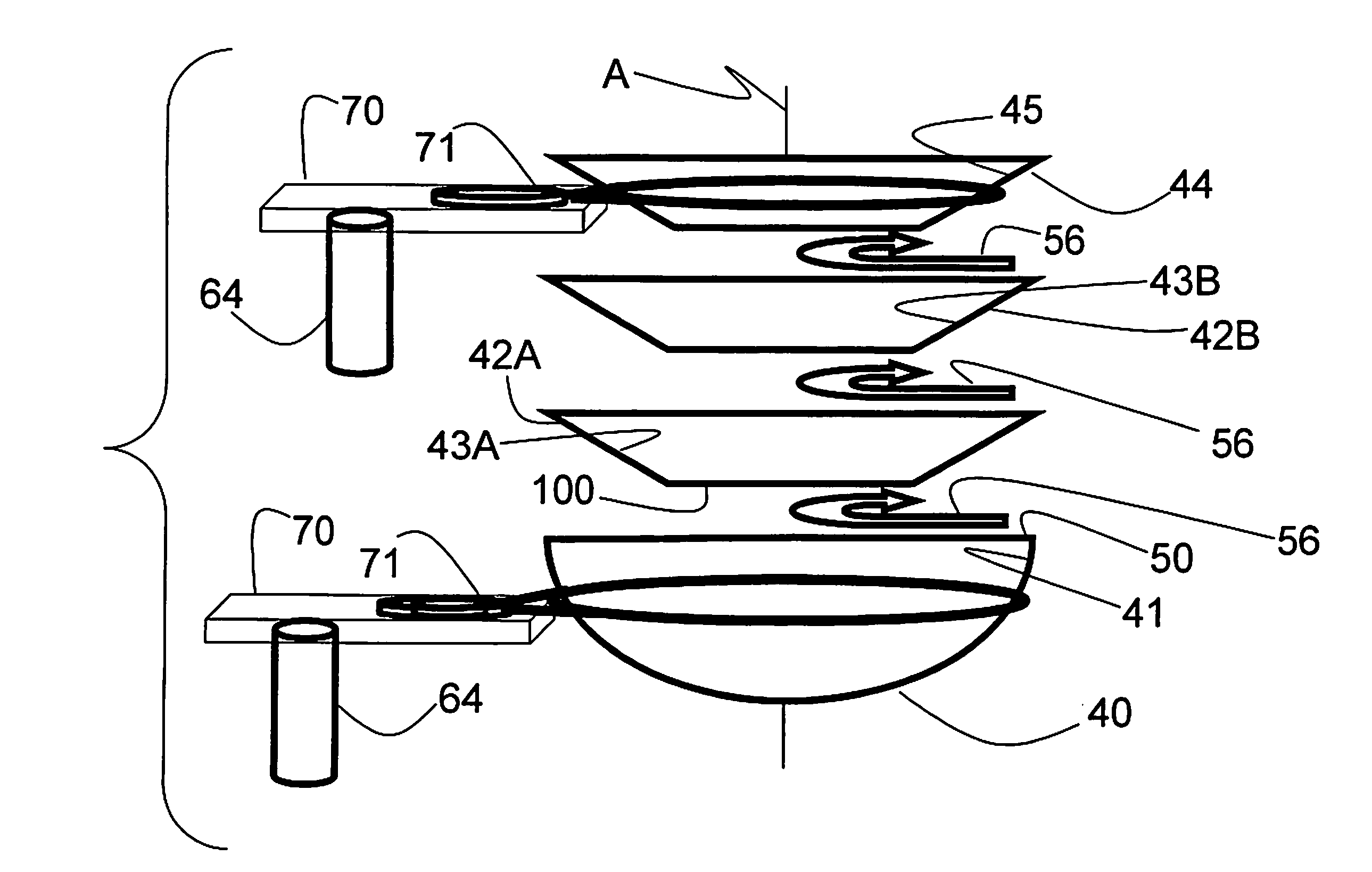
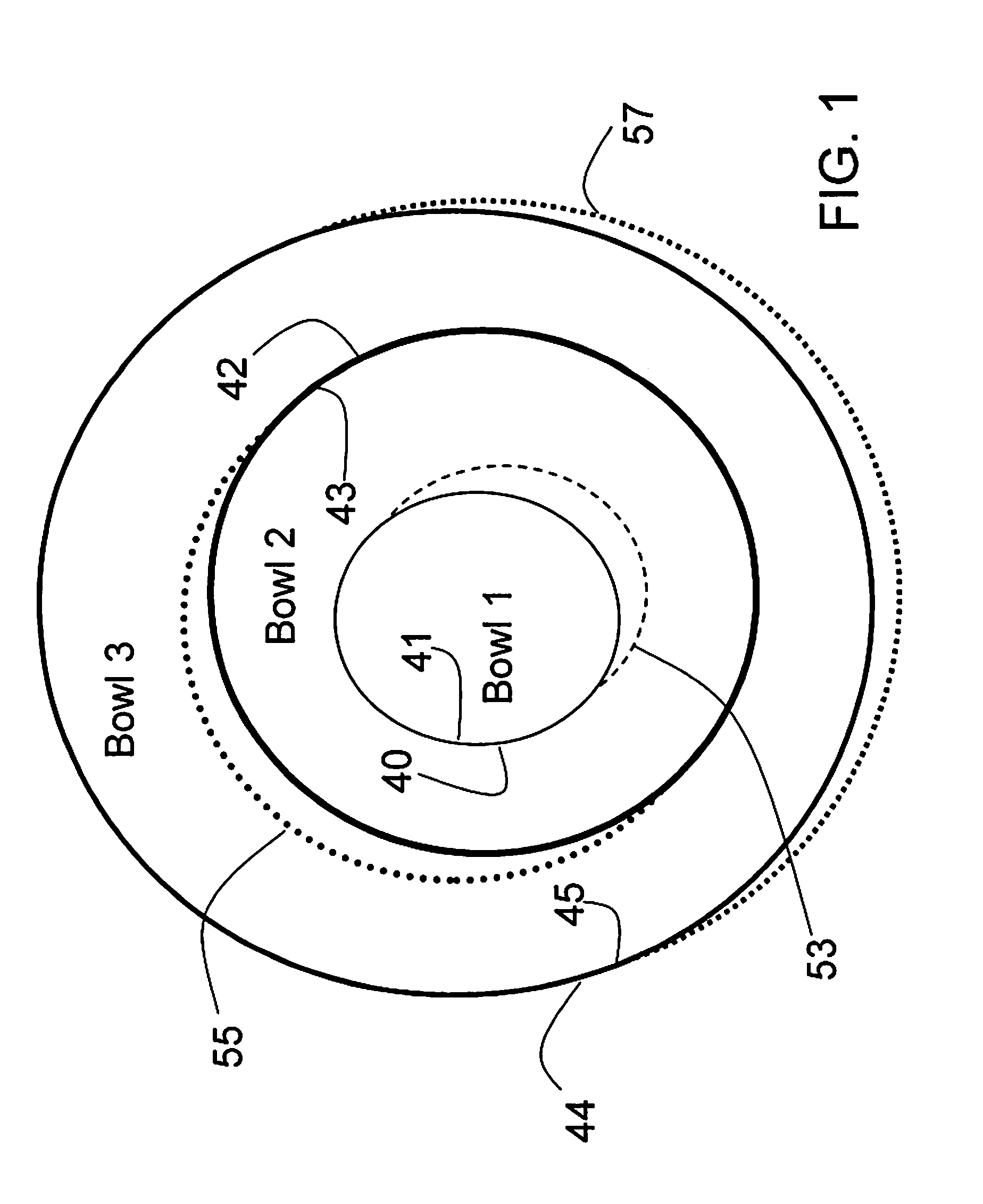
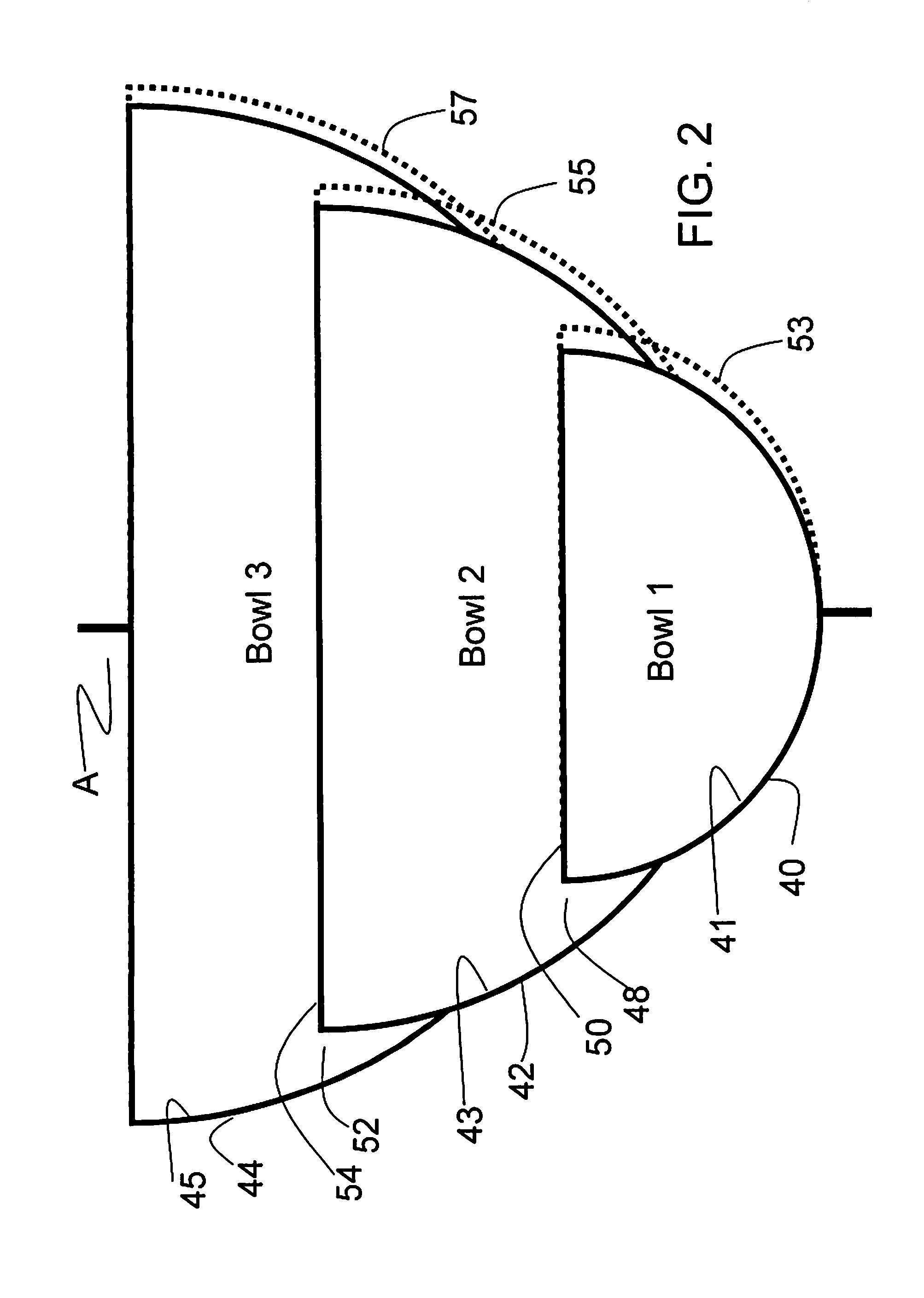
[0062]The Discontinuity embodiment may be represented by a series of bowl shapes. A two bowl embodiment would be a stacked larger bowl completely shadowing the smaller bowl. The smaller bowl would have a “tube-like” structure penetrating from the inner surface of the larger bowl. The ball bearing gains velocity in the smaller bowl before entering the tube structure to be transported onto the inner surface of the larger bowl. This transfer is at a low angle of attack (glancing, not bouncing off, and captured onto the inner surface of the larger bowl). The two bowls are gyrating at the different frequencies, and with different radii of gyration. The smaller bowl would have the larger radius of gyration. It is important to provide an adequate dynamic envelop so that the bowls don't ever touch as they...


PUM


Abstract

Gyration induced acceleration of a mass is modified by inserting changes in the pathway of a mass under the influence of gyration force resulting in an acceleration to re-phase after the phase disruption.

Description

CROSS REFERENCE TO RELATED APPLICATION[0001]This application is based upon and claims the benefit of U.S. Provisional Patent Application No. 61 / 628,590 filed Nov. 2, 2011.BACKGROUND OF THE INVENTION[0002]Mass subjected to a radial force will accelerate. Rotations and gyrations are two techniques to induce radial force. Gyration induced acceleration of a mass by a structure moving in a gyration mode is well understood; water inside a Hula Hoop is an example of a mass accelerated by the hoop structure which in turn is driven by a child's gyrating body. See for example U.S. Pat. No. 5,699,779. Simplified equations of motion for the mass reduce to a phase lock solution if initial conditions are satisfied. Satisfying the Hula-Hoop initial conditions to phase lock the water to the structure involves a ramping up in gyration frequency and gyration radius for the Hula Hoop. More complex mathematical equations include friction and drag, and produce a motion for the mass that is “approximatel...

Claims


Application Information

Patent Timeline
IPC IPC(8): F41B3/04
CPCH02G1/06A61B2017/00345A61B2018/062F41B3/04A63B21/0608A61B17/22
Inventor WESTMEYER, PAULMAZAHERI, RENEE
Owner WESTMEYER PAUL
Learn More