
Method and apparatus for artificial lift using well fluid electrolysis

a technology of fluid electrolysis and artificial lift, which is applied in the direction of fluid removal, earthwork drilling and mining, borehole/well accessories, etc., can solve the problems of insufficient hydrocarbon pressure in the hydrocarbon-bearing formation, inability to meet the needs of artificial lift, and high construction cost of fixed gas injection systems with pipelines to reliable gas production sources or on-site systems with storage facilities in a remote location, etc., to achieve the effect of artificial li

Active Publication Date: 2013-05-02
SAUDI ARABIAN OIL CO
View PDF8 Cites 13 Cited by
  • Summary
  • Abstract
  • Description
  • Claims
  • Application Information

AI Technical Summary

Benefits of technology

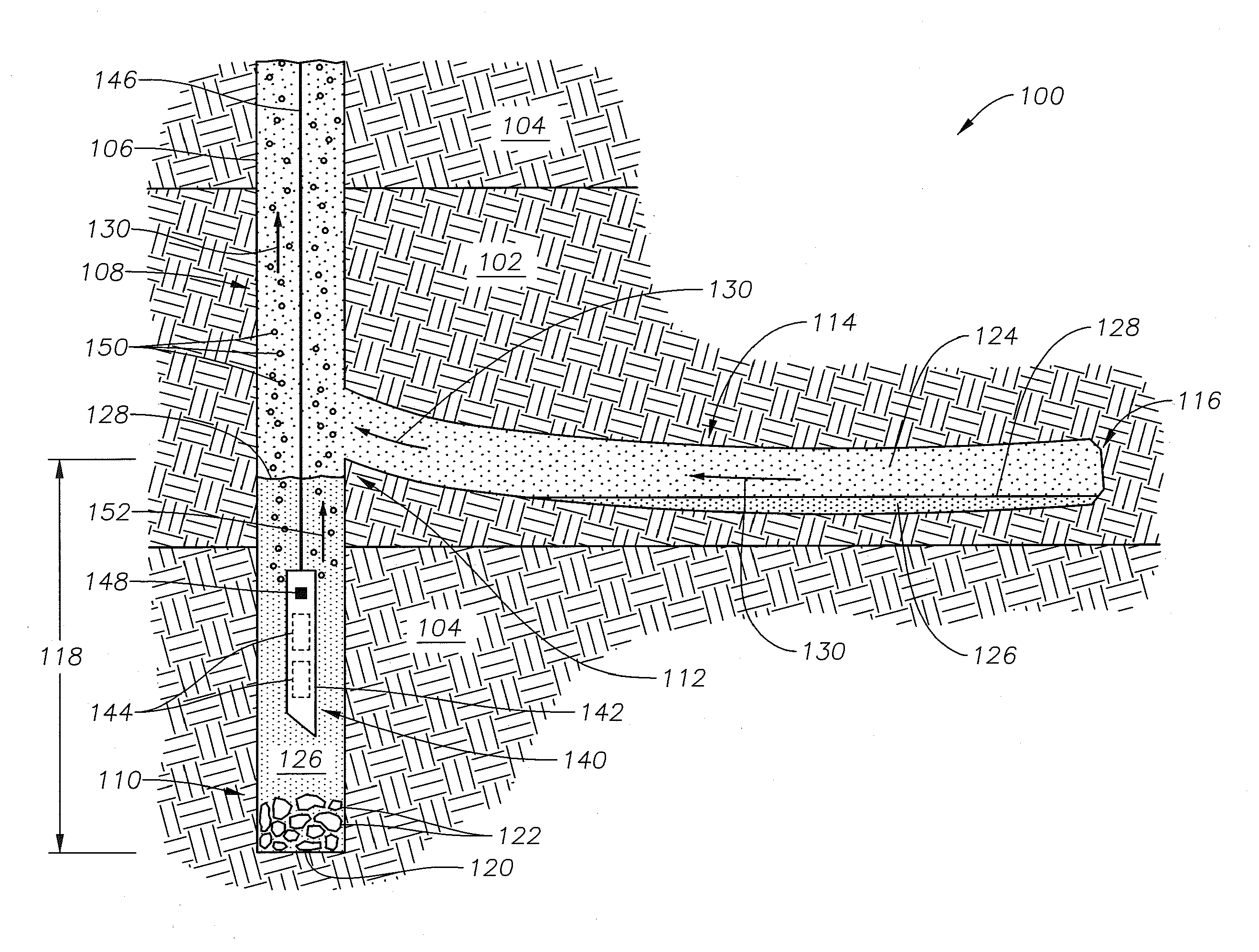
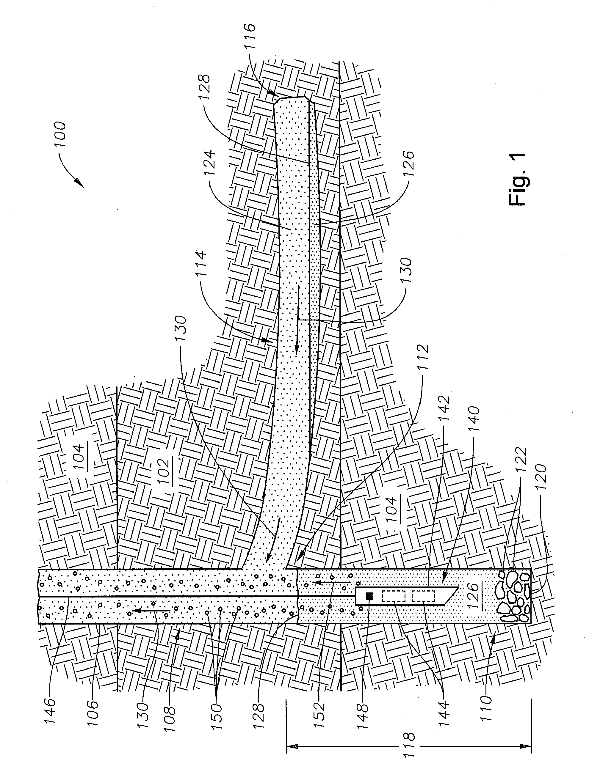
The patent describes a process called artificial lift that helps to increase the production of oil and gas from underground wells. This process works by using gas bubbles that are formed downhole and then move up the well. The gas bubbles push against the liquid in the well, reducing the pressure and allowing more fluid to flow out of the well. This lowers the density of the fluid and allows more oil and gas to be produced from the well.

Problems solved by technology

At a certain point, the pressure present in the hydrocarbon-bearing formation is no longer sufficient to produce hydrocarbon fluid at a desirable hydrocarbon fluid flow rate.
Current gas lift systems suffer from major flaws.
First, they require a constant and large source of compressible gas to inject into the well to provide an effective amount of fluid lift downhole.
A fixed gas injection system with a pipeline to a reliable gas production source or an on-site system with storage facilities in a remote location is very expensive to construct and can be operationally unreliable.
Second, the compressed gas, pressurized to overcome the fluid head pressure at the point of discharge downhole, is cold—possibly well below the freezing temperature of water.
Clathrates tend to build up against cold surfaces and block fluid flow pathways.
Production downtime and intervention to break apart a frozen well bore is expensive.
Finally, the selection of injection gases is problematic.
These compounds can also form reactive species in the well bore environment that interact with the hydrocarbon and non-hydrocarbon bearing formation in undesirable ways.
Pre-refined and on-site separated atmospheric gas processing is expensive, requiring specialized transportation, storage and pre-heating facilities before use.

Method used


Image

  • Method and apparatus for artificial lift using well fluid electrolysis
  • Method and apparatus for artificial lift using well fluid electrolysis
  • Method and apparatus for artificial lift using well fluid electrolysis

Examples


Embodiment Construction

[0018]The Specification, which includes the Summary of Invention, Brief Description of the Drawings and the Detailed Description of the Preferred Embodiments, and the appended Claims refer to particular features (including process or method steps) of the invention. Those of skill in the art understand that the invention includes all possible combinations and uses of particular features described in the Specification. Those of skill in the art understand that the invention is not limited to or by the description of embodiments given in the Specification. The inventive subject matter is not restricted except only in the spirit of the Specification and appended Claims.

[0019]Those of skill in the art also understand that the terminology used for describing particular embodiments does not limit the scope or breadth of the invention. In interpreting the Specification and appended Claims, all terms should be interpreted in the broadest possible manner consistent with the context of each te...


PUM


Abstract

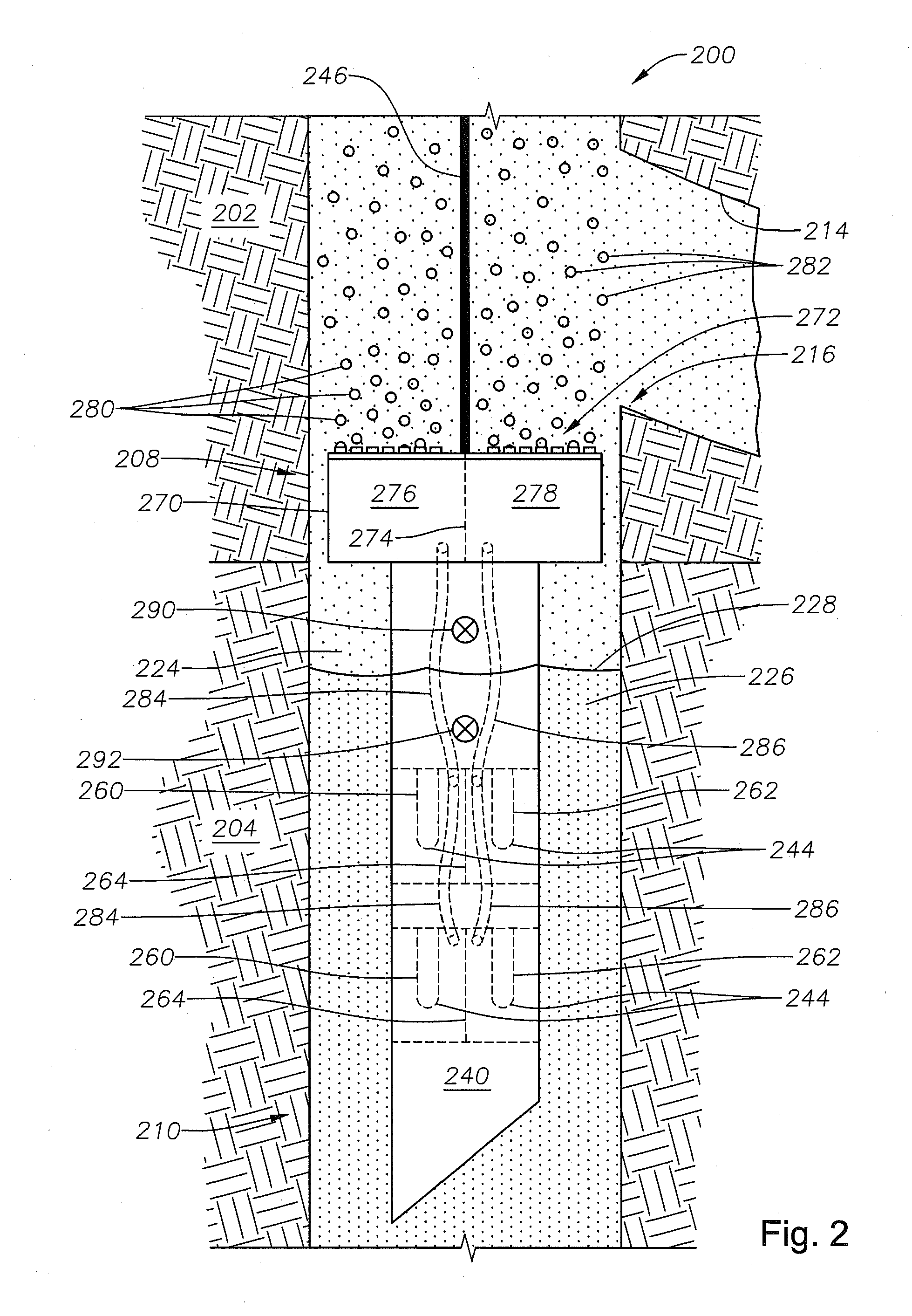
An artificial lift device is useful for inducing artificial gas lift in a well bore fluid present in a horizontal well bore system using electrically conductive aqueous solution. The artificial lift device includes an ion exchange membrane, an electrode pair having an anode and a cathode separated by the ion exchange membrane, a sensor operable to detect the presence of solution and a power relay operable to selectively permit the electrode pair to receive electrical power. The artificial lift device is operable to form hydrogen product gas bubbles from hydrogen product gas. A method for providing artificial gas lift using the artificial lift device includes forming a horizontal well bore system having a well boot, introducing the artificial lift device into the well bore system, introducing electrical power to the electrode pair, and operating the device to introduce hydrogen product gas bubbles into the horizontal well bore system.

Description

CROSS-REFERENCE TO RELATED PATENT APPLICATIONS[0001]This application claims priority from U.S. Provisional Application No. 61 / 554,567, filed Nov. 2, 2011. For purposes of United States patent practice, this application incorporates the contents of the Provisional Application by reference in its entirety.BACKGROUND OF THE INVENTION[0002]1. Field of the Invention[0003]The field of invention is associated with providing artificial lift to a well producing hydrocarbon fluid. More specifically, the field relates to providing artificial lift using an electrochemical gas lift apparatus and method.[0004]2. Description of the Related Art[0005]At the beginning of the hydrocarbon fluid production cycle, the fluid pressure trapped in the hydrocarbon-bearing formation is operable to drive hydrocarbon fluid to the surface through a pre-formed well bore without additional production assistance. The pressure difference between the fluid head pressure present in the well bore and the pressure of the...

Claims


Application Information

Patent Timeline
IPC IPC(8): E21B43/18
CPCE21B43/122
Inventor NOUI-MEHIDI, MOHAMED NABIL
Owner SAUDI ARABIAN OIL CO
Learn More