Wireless power transmitter and power transmission method thereof

Inactive Publication Date: 2013-05-02
LG INNOTEK CO LTD
View PDF6 Cites 249 Cited by
  • Summary
  • Abstract
  • Description
  • Claims
  • Application Information

AI Technical Summary

Benefits of technology

[0011]According to the embodiment of the disclosure, the wireless power transmitter transmits energy through the transmission resonance unit corresponding to the location of the wireless power receiver, thereby improving the power transmission efficiency.

Problems solved by technology

However, according to the wireless power transmission technology of the related art, power must be constantly transmitted regardless

Method used


Image

  • Wireless power transmitter and power transmission method thereof
  • Wireless power transmitter and power transmission method thereof
  • Wireless power transmitter and power transmission method thereof

Examples


Example

[0020]In the following description, if detailed description about well-known functions or configurations may make the subject matter of the disclosure unclear, the detailed description will be omitted. In addition, terminologies to be described are defined based on functions of components according to the embodiment, and may have meanings varying according to the intentions of a user or an operator and customers. Accordingly, the terminologies should be defined based on the whole context throughout the present specification.

[0021]Hereinafter, the embodiment will be described with reference to accompanying drawings.

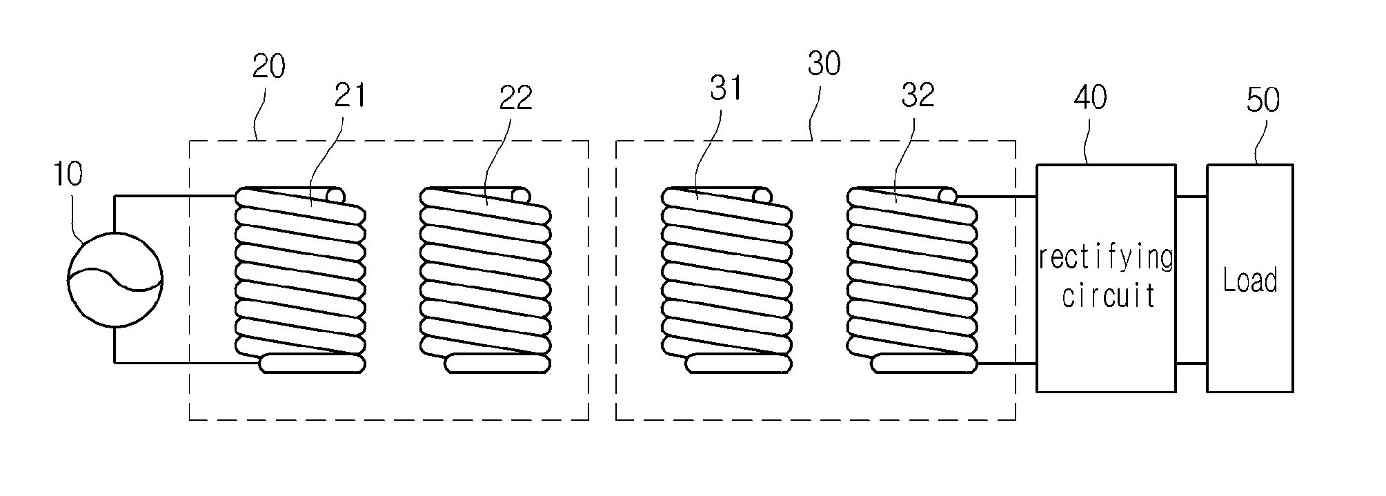
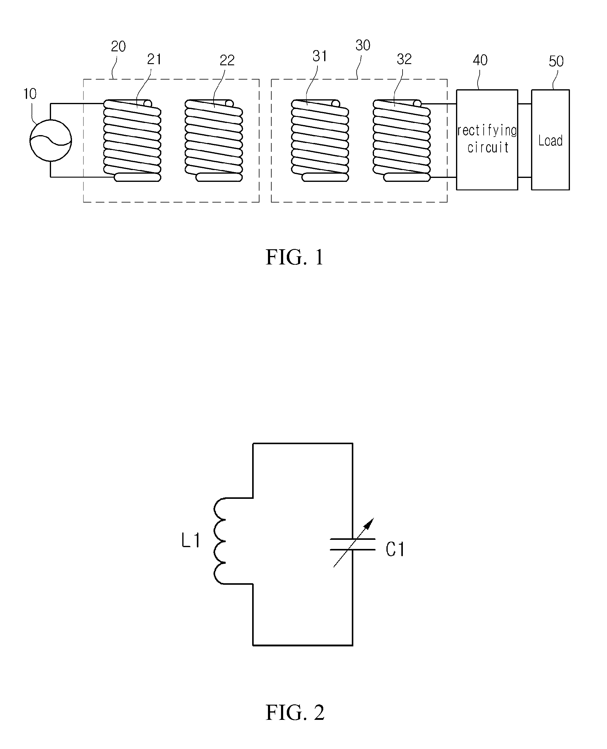
[0022]FIG. 1 is a view showing a wireless power transmission system according to the embodiment.

[0023]Referring to FIG. 1, the wireless power transmission system includes a power source 10, a power transmission unit 20, a power reception unit 30, a rectifying circuit 40 and a load 50.

[0024]The power generated from the power source 10 is provided to the power transmission u...


PUM


Abstract

Disclosed are a wireless power transmitter and a power transmission method thereof. The wireless power transmitter includes a plurality of transmission resonance units, a detection power applying unit applying detection power to the transmission resonance units to detect a location of the wireless power receiver, and a current measuring unit measuring current generating from an inner part of the wireless power transmitter based on the applied detection power. The wireless power transmitter transmits the power through at least one transmitting resonance unit corresponding to the location of the wireless power receiver based on the measured current.

Description

CROSS-REFERENCE TO RELATED APPLICATION[0001]This application claims the benefit under 35 U.S.C. §119 of Korean Patent Application No. 10-2011-0113288, filed Nov. 2, 2011, which is hereby incorporated by reference in its entirety.BACKGROUND[0002]The disclosure relates to a wireless power transmission technology. In more particular, the disclosure relates to a wireless power transmitter capable of effectively transmitting energy by using a resonance phenomenon and a power transmission method thereof.[0003]A wireless power transmission or a wireless energy transfer refers to a technology of wirelessly transferring electric energy to desired devices. In the 1800's, an electric motor or a transformer employing the principle of electromagnetic induction has been extensively used and then a method for transmitting electrical energy by irradiating electromagnetic waves, such as radio waves or lasers, has been suggested. Actually, electrical toothbrushes or electrical razors, which are frequ...

Claims


Application Information

Patent Timeline
IPC IPC(8): H02J17/00
CPCH04B5/0087H04B5/0037H02J50/90H02J50/12H02J50/502H02J50/40
Inventor BAE, SU HOLEE, KI MIN
Owner LG INNOTEK CO LTD
Why Eureka
Try Eureka