Rotor for electrical machine, in particular for a synchronous motor

a technology of synchronous motors and rotors, which is applied in the direction of magnetic circuit rotating parts, magnetic circuit shape/form/construction, transportation and packaging, etc., can solve the problems of complex and costly construction, even more complex and heavier construction of rotors

Inactive Publication Date: 2013-05-02
BRUSA ELECTRONICS AG
View PDF9 Cites 21 Cited by
  • Summary
  • Abstract
  • Description
  • Claims
  • Application Information

AI Technical Summary

Benefits of technology

[0025]As a result of the high rotational speeds, large radial forces act on the coils which are passed via the end caps to the support ring which can readily absorb this stress, according to the invention and as a result of its closed annular geometry. The support ring can additionally be provided with a balancing ring or with balancing elements so that the support ring also serves as a basis for the dynamic balancing of the rotor. Preferably in a structure-simplifying manner and according to the invention, the function of balancing is hereby integrated directly in the support ring because the balancing quality is thereby rigidly connected to the rotor construction and need not be transferred via an additional path, say an additional component with additional interfaces. Balancing weights for the fine balancing of the complete rotor can therefore be mounted on the supporting feet of the support ring and / or on the support ring itself or on the additional balancing ring, which is an additional advantage of the invention with synergistic effect. Alternatively, a local accumulation of material can be provided which results in the necessary balancing quality by local removal of material, e.g. by holes, grinding or milling.
with synergistic effect. Alternatively, a local accumulation of material can be provided which results in the necessary balancing quality by local removal of material, e.g. by holes, grinding or milling.

Problems solved by technology

The above arrangement on the one hand requires a complex and costly construction, on the other hand the windings there and the support elements must be machined with small tolerance, which is problematical from the production technology viewpoint.
Since, however, this comprises a superconducting generator rotor and not a generator or motor which can be used in manifold ways in large numbers, such as for electromobility for example, the necessary expenditure plays a minor role.
Due to the use of the additional metal tube can, however, the rotor has an even more complex and heavier constructions which is associated with high production technology demands.

Method used


Image

  • Rotor for electrical machine, in particular for a synchronous motor
  • Rotor for electrical machine, in particular for a synchronous motor
  • Rotor for electrical machine, in particular for a synchronous motor

Examples


Embodiment Construction

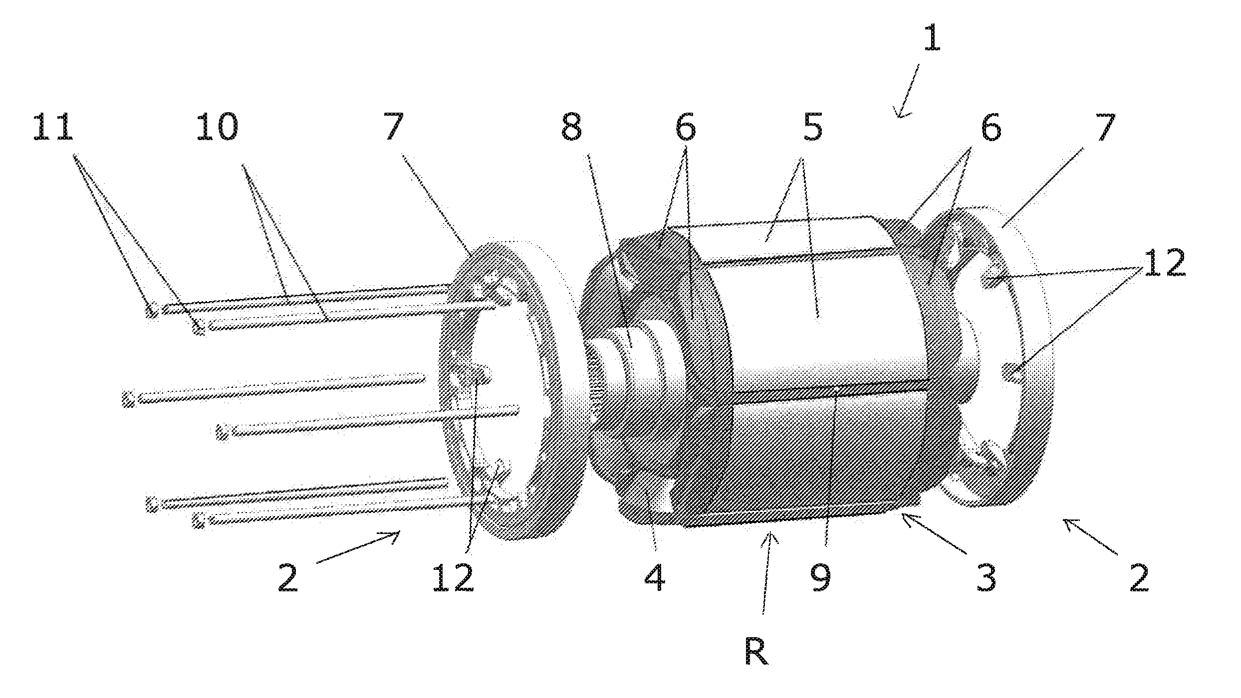
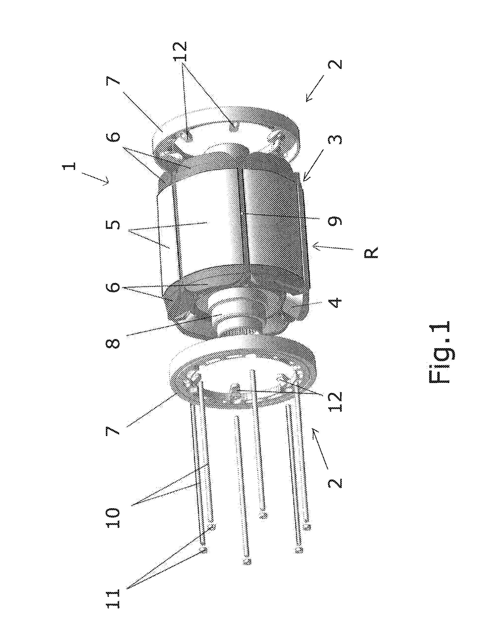
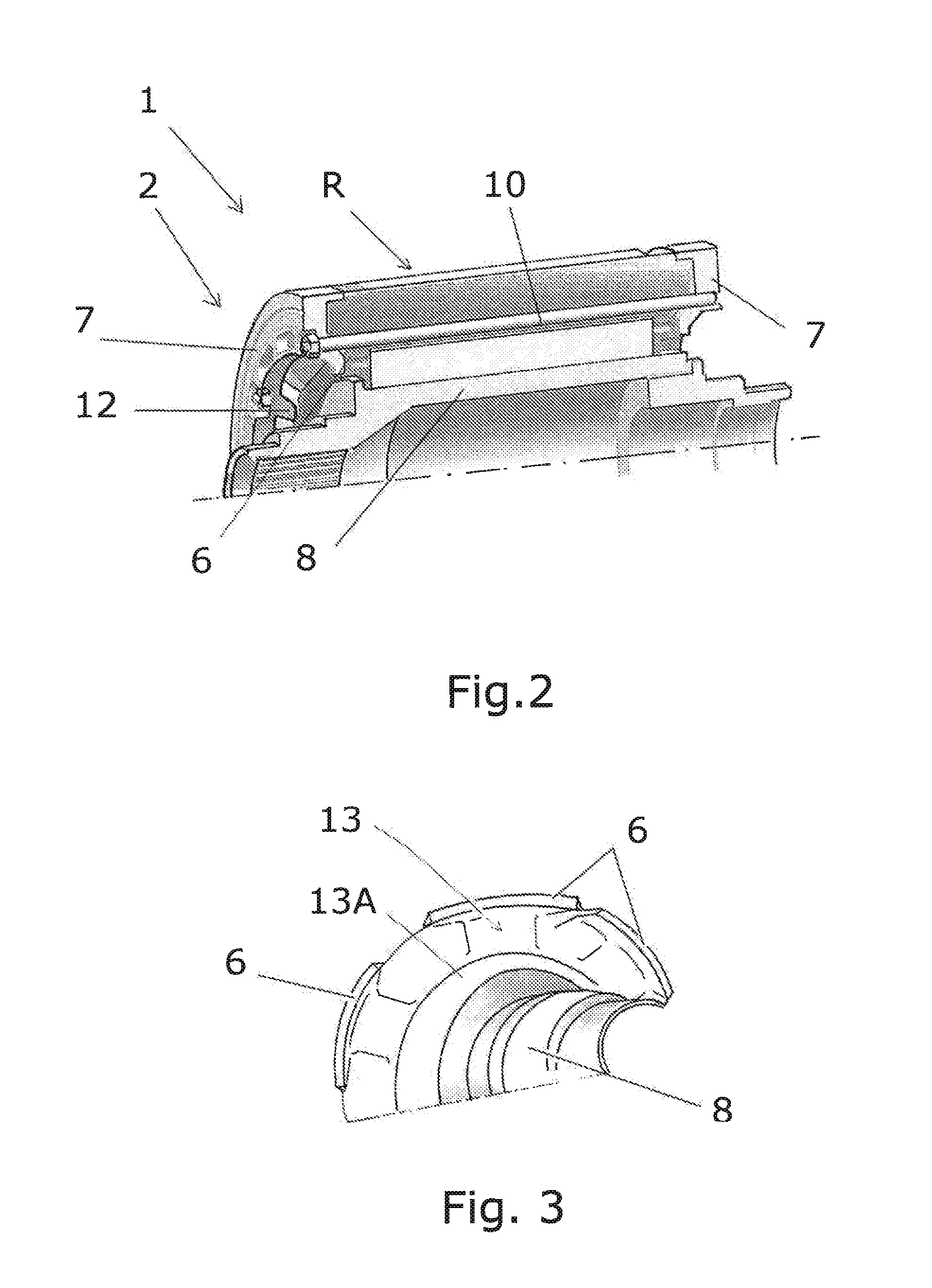
[0031]FIG. 1 shows a rotor stack 1 according to the invention comprising a rotor R and an exemplary embodiment of a proposed restraining system 2 in an exploded view. The restraining system 2 according to the invention comprises inner end caps 6 and respectively one outer support ring 7 on both sides and is substantially provided as a protecting device in order to adequately support the winding heads 4 projecting from a sheet stack 3 in the axial direction on both front sides of the rotor 6, and possibly winding regions which emerge between pole shoes 5 of the rotor R, even at higher rotational speeds of the rotor R. In FIG. 1 a shaft of the rotor R is designated with 8.

[0032]The rotor stack 1 provided with the restraining system 2 according to the invention is particularly suited for a rotor R of a current-excited synchronous motor (SSM) or another electric motor having a winding on the rotor, in particular for vehicle drives and at the same time in particular for mass production.

[...


PUM


Abstract

Electrical machine rotors (R) suited for synchronous motors of electric vehicle drives. A rotor (R) includes a rotor shaft (8), a sheet stack (3), windings, and a restraining system (2) with support elements. The support elements of the restraining system include support rings (7) to protect winding heads (4) projecting from the sheet stack (3) in the axial direction against radial stresses. The elements of the restraining system (2) protecting the winding heads (4) from stresses also include axially inner end caps (6) configured as supports for the finished winding heads (4) in the operating state, and as guides and supports during the winding of the pole windings of the rotor (R) about the axial edge of the sheet stack (3). The axially outer support rings (7) cooperate with the axially inner end caps (6) so that the support rings (7) may absorb centrifugal forces acting on winding heads (4) end caps (6).

Description

[0001]This application is a 35 U.S.C. 371 national-phase entry of PCT International application no. PCT / IB2011 / 053152 filed on Jul. 14, 2011 and also claims benefit of priority to European application no. EP10169565 filed on Jul. 14, 2010, and also claims benefit of priority as a non-provisional of U.S. provisional application Ser. No. 61 / 364,439 filed on Jul. 15, 2010, and parent application PCT / IB2011 / 053152, European application no. EP10169565 and U.S. provisional application Ser. No. 61 / 364,439 are all incorporated herein by reference in their respective entireties, as to all their parts, for all intents and purposes, as if identically set forth in full herein.TECHNICAL FIELD OF THE INVENTION[0002]The present invention relates to a rotor construction for an electrical machine, in particular a synchronous motor of electric vehicle drives, wherein the rotor comprises a rotor shaft, a sheet stack, windings, and a restraining system with support elements.PRIOR ART[0003]When the roto...

Claims


Application Information

Patent Timeline
Patent Type & Authority Applications(United States)
IPC IPC(8): H02K3/51H02K9/06
CPCH02K3/38H02K3/527H02K7/04H02K3/51H02K15/165Y02T10/641H02K9/06Y02T10/64H02K3/52H02K15/16H02K1/22
Inventor HOLZNER, ANDREAS
Owner BRUSA ELECTRONICS AG
Why Eureka
Try Eureka