
Resistive foil edge grading for accelerator and other high voltage structures

a technology of resistive foil and high voltage structure, which is applied in the direction of variable capacitor, fixed capacitor details, fixed capacitors, etc., can solve the problems of limiting the ability to build compact high voltage systems, insulators to fail at significantly lower electric potentials than, and internal bulk breakdown of materials, so as to reduce electric field stress

Inactive Publication Date: 2013-05-02
LAWRENCE LIVERMORE NAT SECURITY LLC
View PDF6 Cites 13 Cited by
  • Summary
  • Abstract
  • Description
  • Claims
  • Application Information

AI Technical Summary

Benefits of technology

The invention is about a device that stores or transmits electrical energy using a layered structure. The device includes a resistive layer that helps to reduce electric field stress at the edge of a conductor when a high voltage is applied across the conductor. This helps to improve the stability and reliability of the device. The method involves placing the resistive layer on the insulating layer and creating a path for the electric current to flow through. This results in a more even distribution of electric current and helps to reduce the risk of electrical arcing.

Problems solved by technology

This enhanced field causes the insulator to fail at significantly lower electric potentials than it would without such field enhancement.
The problem becomes more serious as the thickness of the conductors decreases, setting a limit on the electric field gradients that can be achieved, with a resulting limit on the ability to build compact high voltage systems.
A failure of the material would result in an internal bulk breakdown of the material.
Breakdowns of this type occur very rapidly.
However, these techniques have not been totally effective in combating the enhanced edge fields.

Method used


Image

  • Resistive foil edge grading for accelerator and other high voltage structures
  • Resistive foil edge grading for accelerator and other high voltage structures
  • Resistive foil edge grading for accelerator and other high voltage structures

Examples


Embodiment Construction

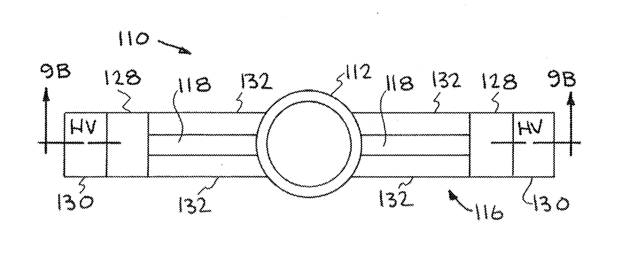
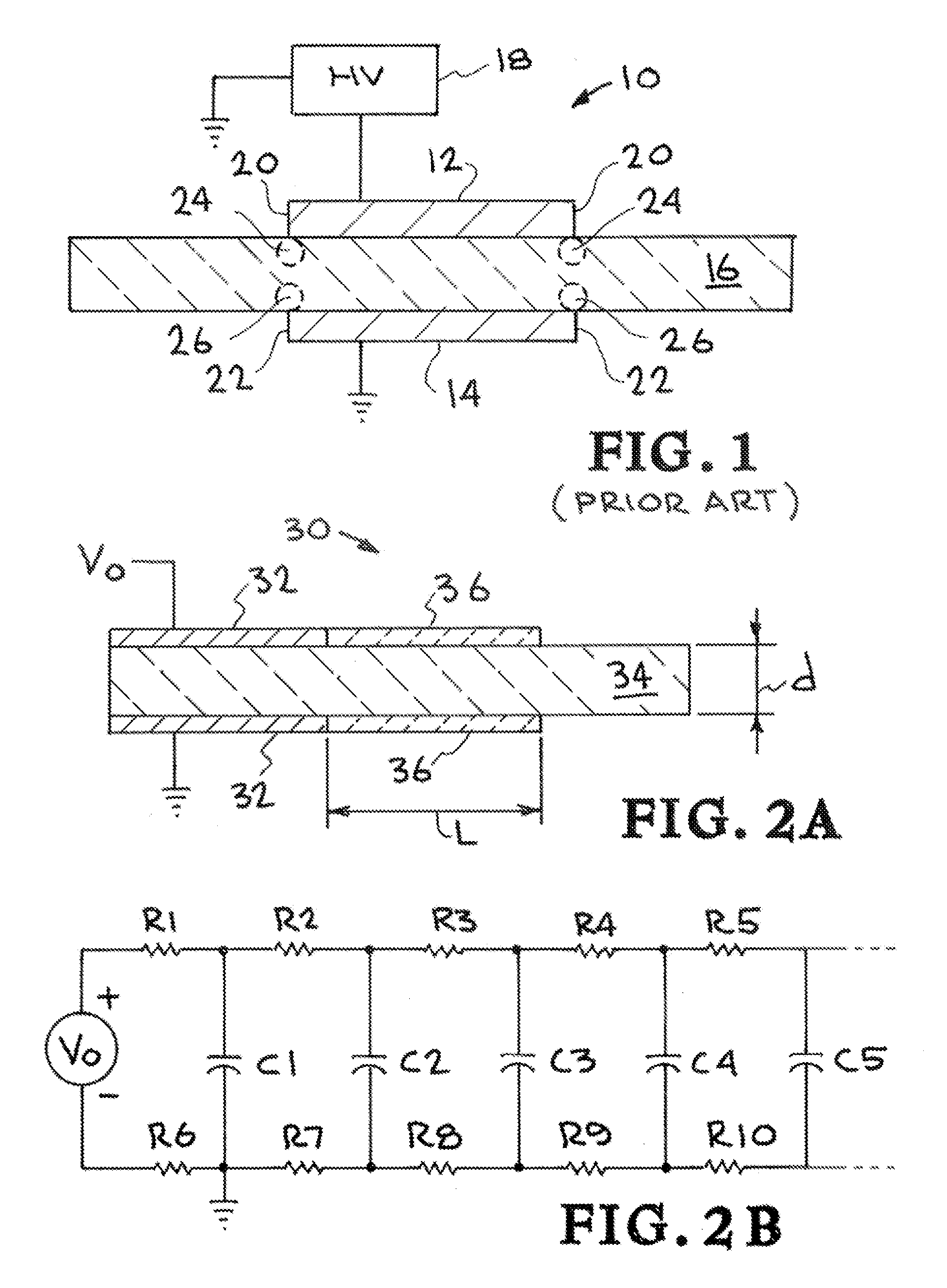
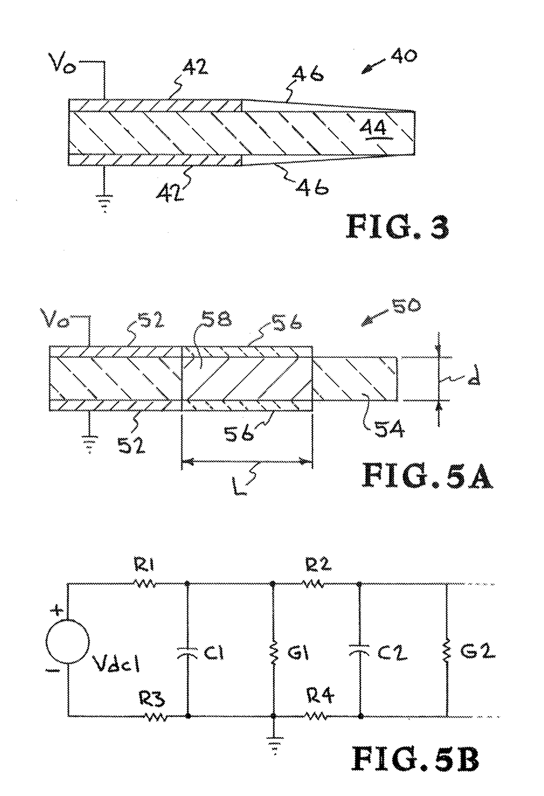
[0027]Referring more specifically to the drawings, for illustrative purposes the present invention is embodied in the apparatus and method generally shown in FIGS. 2A, B through FIG. 9A, B. It will be appreciated that the apparatus may vary as to configuration and as to details of the parts, and the method may vary as to its particular implementation, without departing from the basic concepts as disclosed herein.

[0028]The invention applies to basic energy storage and transmission structures or devices, particularly compact structures or devices designed to receive high energy. The essential elements of these structures or devices are a pair of electrical conductors, separated by an insulator, across which a voltage is placed.

[0029]FIG. 1 shows a basic structure or device 10 formed of conductors 12, 14 on opposite sides of an insulator 16. A high voltage (HV) source 18 is connected across the two conductors 12, 14. Conductors 12, 14 are typically made of metal. Insulator 16 may be a ...


PUM


Abstract

In a structure or device having a pair of electrical conductors separated by an insulator across which a voltage is placed, resistive layers are formed around the conductors to force the electric potential within the insulator to distribute more uniformly so as to decrease or eliminate electric field enhancement at the conductor edges. This is done by utilizing the properties of resistive layers to allow the voltage on the electrode to diffuse outwards, reducing the field stress at the conductor edge. Preferably, the resistive layer has a tapered resistivity, with a lower resistivity adjacent to the conductor and a higher resistivity away from the conductor. Generally, a resistive path across the insulator is provided, preferably by providing a resistive region in the bulk of the insulator, with the resistive layer extending over the resistive region.

Description

GOVERNMENT RIGHTS[0001]The United States Government has rights in this invention pursuant to Contract No. DE-AC52-07NA27344 between the U.S. Department of Energy and Lawrence Livermore National Security, LLC, for the operation of Lawrence Livermore National Laboratory.BACKGROUND OF THE INVENTION[0002]1. Field of the Invention[0003]This invention pertains generally to high voltage structures or devices including structures or devices for storing or transmitting electrical energy, and more particularly to reducing electric fields at the edges of conductors on insulators in these high voltage structures or devices.[0004]2. Description of Related Art[0005]When an insulator is placed between two conductors, typically metal, and the conductors are energized with high voltage, the electric field in the insulator reaches a maximum at the edges of the conductors. This enhanced field causes the insulator to fail at significantly lower electric potentials than it would without such field enhan...

Claims


Application Information

Patent Timeline
Patent Type & Authority Applications(United States)
IPC IPC(8): H05H7/00B05D5/12H01G4/255
CPCH05H9/005
Inventor CAPORASO, GEORGE J.SAMPAYAN, STEPHAN E.SANDERS, DAVID M.
Owner LAWRENCE LIVERMORE NAT SECURITY LLC
Learn More