Epoxy pouring type current transformer and manufacturing method thereof

A current transformer, epoxy casting technology, applied in the manufacture of inductors/transformers/magnets, inductors, circuits, etc., can solve the problems of easy detachment, high production cost, poor packaging, etc., to achieve good conversion current and improve dynamic stability. sexual effect

Active Publication Date: 2022-07-29
JIANGSU JINGJIANG INSTR TRANSFORMER FACTORY
View PDF8 Cites 0 Cited by
  • Summary
  • Abstract
  • Description
  • Claims
  • Application Information

AI Technical Summary

Problems solved by technology

The existing technology has the following problems: 1. After the winding of the primary and secondary windings is completed, the primary and secondary windings are respectively covered with a buffer layer first, and then covered with a semi-conductive layer for overall shielding to ensure the partial discharge level. It is complicated, and the shape of the primary conductor is a square mechanism. It is very time-consuming to wrap the buffer layer. After the buffer layer is wrapped, it is easy to form an irregular shape. Low work efficiency, low output, etc., and high production costs; 2. The primary winding must pass through the iron core. The existing production method is that the primary conductor directly passes through the center hole of the secondary winding, and the concentricity cannot meet the requirements after casting , which is not conducive to generating a uniform electric field

Method used


Image

  • Epoxy pouring type current transformer and manufacturing method thereof
  • Epoxy pouring type current transformer and manufacturing method thereof

Examples


Embodiment 1

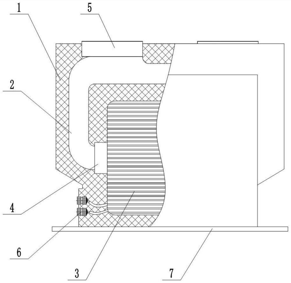
[0045] An epoxy casting type current transformer includes an epoxy resin body 1, a primary winding 2, and a secondary winding 3. The primary winding 2 includes a primary conductor 201 and an insulating layer wrapped on the primary conductor 201. The primary winding The lower side of 2 is concentrically sleeved with an insulating round tube 4, and the lower side and the insulating round tube 4 pass through the center hole of the secondary winding 3 concentrically, and the insulating round tube 4 is wrapped with a semi-conductive self-adhesive tape, and the primary winding 2. The top is provided with a primary terminal 5, the primary terminal 5 is connected to the primary winding 2, the primary terminal 5 protrudes from the top of the epoxy resin body 1, and the bottom of the epoxy resin body 1 is provided with a secondary terminal 6, so The secondary terminal 6 is connected to the secondary winding 3 through a wire. The secondary winding 3 includes an iron core and a secondary c...

Embodiment 2

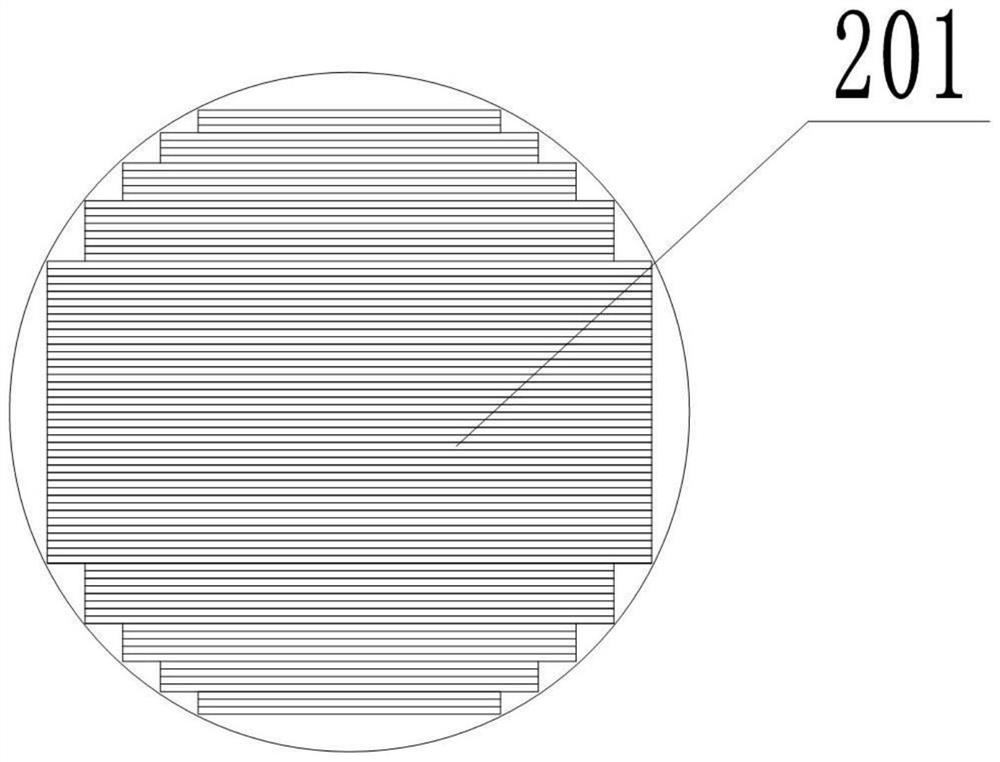
[0053] An epoxy casting type current transformer includes an epoxy resin body 1, a primary winding 2, and a secondary winding 3. The primary winding 2 includes a primary conductor 201 with a symmetrical stepped structure and an insulating layer wrapped on the primary conductor 201. , the lower side of the primary winding 2 is concentrically sleeved with an insulating round tube 4, and the lower side and the insulating round tube 4 pass through the center hole of the secondary winding 3 concentrically, and the insulating round tube 4 is wrapped with semi-conductive crepe paper, The top of the primary winding 2 is provided with a primary terminal 5, the primary terminal 5 is connected to the primary winding 2, the primary terminal 5 protrudes from the top of the epoxy resin body 1, and the bottom of the epoxy resin body 1 is provided with a secondary terminal. Terminal 6, the secondary terminal 6 is connected to the secondary winding 3 through a wire, the secondary winding 3 incl...


PUM


Abstract

The invention provides an epoxy pouring type current transformer which comprises an epoxy resin body (1), a primary winding (2) and a secondary winding (3), the lower edge of the primary winding (2) is sleeved with an insulating round tube (4), the lower edge and the insulating round tube (4) concentrically penetrate through a center hole of the secondary winding (3), the insulating round tube (4) is wrapped with a semi-conductive layer, and the semi-conductive layer is wrapped with an insulating layer. And the bottom of the epoxy resin main body (1) is connected with a mounting bottom plate (7). The device is simple in structure, convenient to operate and capable of improving the partial discharge level of a product. The invention further provides a manufacturing method of the epoxy pouring type current transformer. The manufacturing method comprises the following steps of iron core buffering and binding, secondary winding (3) winding, primary winding (2) winding, primary terminal (5) welding and pouring. The process steps are simple, the working efficiency is high and the cost is low.

Description

technical field [0001] The invention relates to the field of current transformers, in particular to an epoxy casting type current transformer and a manufacturing method thereof. Background technique [0002] Epoxy casting current transformer is composed of primary winding and secondary winding, which are then cast with epoxy resin mixture. The prior art has the following problems: 1. After the winding of the primary and secondary windings is completed, first wrap the buffer layer on the primary and secondary windings, and then wrap the semi-conductive layer for overall shielding to ensure the partial discharge level, and the operation It is complicated, and the shape of the primary conductor is a square structure. It is very time-consuming to wrap the buffer layer. After the buffer layer is wrapped, it is easy to form an irregular shape. When wrapping the semiconductive layer, it will also cause poor wrapping and easy detachment. Low work efficiency, low output, etc., and t...

Claims


Application Information

Patent Timeline
Patent Type & Authority Applications(China)
IPC IPC(8): H01F38/28H01F38/30H01F41/00
CPCH01F38/28H01F38/30H01F41/00
Inventor 杜桂芬印丽琴朱琦沈莉
Owner JIANGSU JINGJIANG INSTR TRANSFORMER FACTORY
Why Eureka
Try Eureka