Rooftop high-efficiency gas furnace control with condensate management

a gas furnace and high-efficiency technology, applied in process control, lighting and heating apparatus, instruments, etc., can solve problems such as premature failure of heat exchanger surfaces and other components in the flue stream, and affecting the efficiency of non-condensing furnaces, etc., to achieve the effect of improving efficiency

Inactive Publication Date: 2013-05-02
HVAC MODULATION TECH
View PDF14 Cites 15 Cited by
  • Summary
  • Abstract
  • Description
  • Claims
  • Application Information

AI Technical Summary

Benefits of technology

[0010]Third, in some embodiments of this invention, at least one or at least two water level indication sensors, such as pressure switches or conductance probes, each is used to indicate when the condensate fluid reaches a maximum level to activate a drainage cycle, for example when the drain valve opens, and / or reaches a minimum level to terminate a drainage cycle, for example when the drain valve closes. In some embodiments of this invention, the maximum level of condensate fluid is designed or set so that the condensate level does not become excessive and cause an overflow at the condensate collector box but also can indicate a level of substantial volume to insure a freeze-free drainage cycle. In some embodiments of this invention, the minimum level is designed so that the condensate collector box does not empty completely, insuring a constant trapping action, for example to prevent sewage gases from escaping the drain system, such as into a furnace flue path. The minimum level according to some embodiments of this invention is designed to accommodate an anticipated negative pressure in the condensate collector box, particularly without bypass and possible freezing during a system off-cycle, for example to avoid damage due to expansion caused by freezing water.
[0012]Fifth, in some embodiments of this invention, a temperature sensor in the incoming air stream at or near the primary heat exchanger is used to monitor the return air temperature, for example as the air passes over or across the heat exchanger. In some embodiments of this invention, the outdoor air is introduced via an economizer or a make-up air application, and thus the efficiency of the furnace increases to a point that causes or forms condensation in the primary heat exchanger, which can lead to corrosion and premature failure of parts or components. In some embodiments of this invention, the sensor provides temperature status or other information to the controller, for example, to change or adjust the air-fuel mixture and / or to maintain a proper efficiency during the operation mode.

Problems solved by technology

Conventional mid-efficiency, non-condensing furnaces are limited to steady state efficiencies of 83% or less to limit corrosion in flue passages which causes premature failure of heat exchanger surfaces and other components in the flue stream.
Extreme temperatures, such as extreme heat during the cooling season or extreme cold during the heating season, can challenge the system design.
For conventional installations using gas-fired forced air furnaces integrated into the rooftop equipment, upgrading the furnace to a high-efficiency design can be restricted or limited in view of difficulties with managing and disposing of the condensate produced by the conventional appliances.
Some design challenges arise, for example, when trying to prevent the condensate from freezing in any part of the system, because providing a drain line and trap impervious to cold ambient conditions and insuring that the furnace efficiency does not increase due to colder incoming air over the heat exchanger can cause condensation in portions of the furnace that are not designed to handle the condensate produced.

Method used


Image

  • Rooftop high-efficiency gas furnace control with condensate management
  • Rooftop high-efficiency gas furnace control with condensate management
  • Rooftop high-efficiency gas furnace control with condensate management

Examples


Embodiment Construction

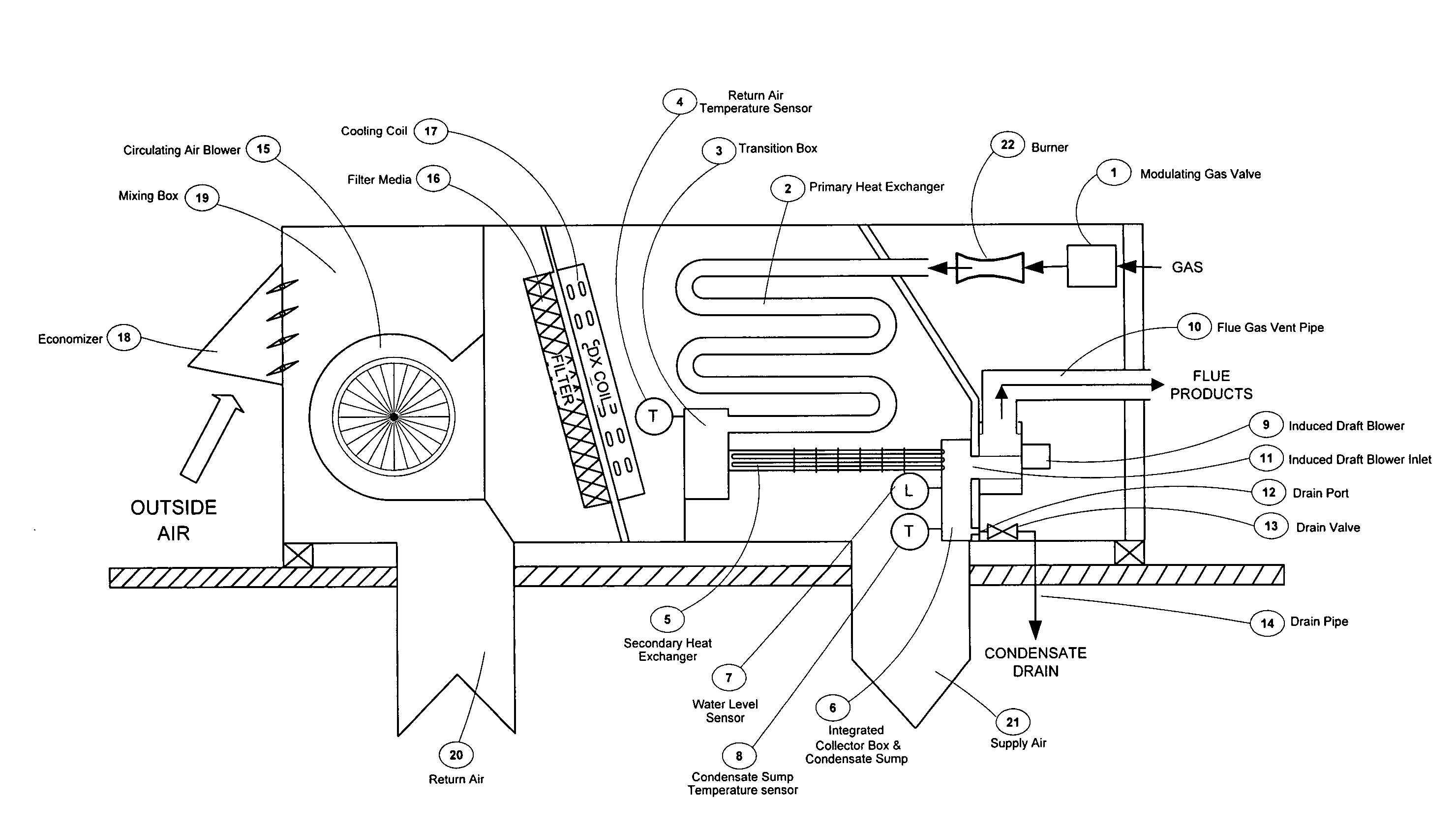
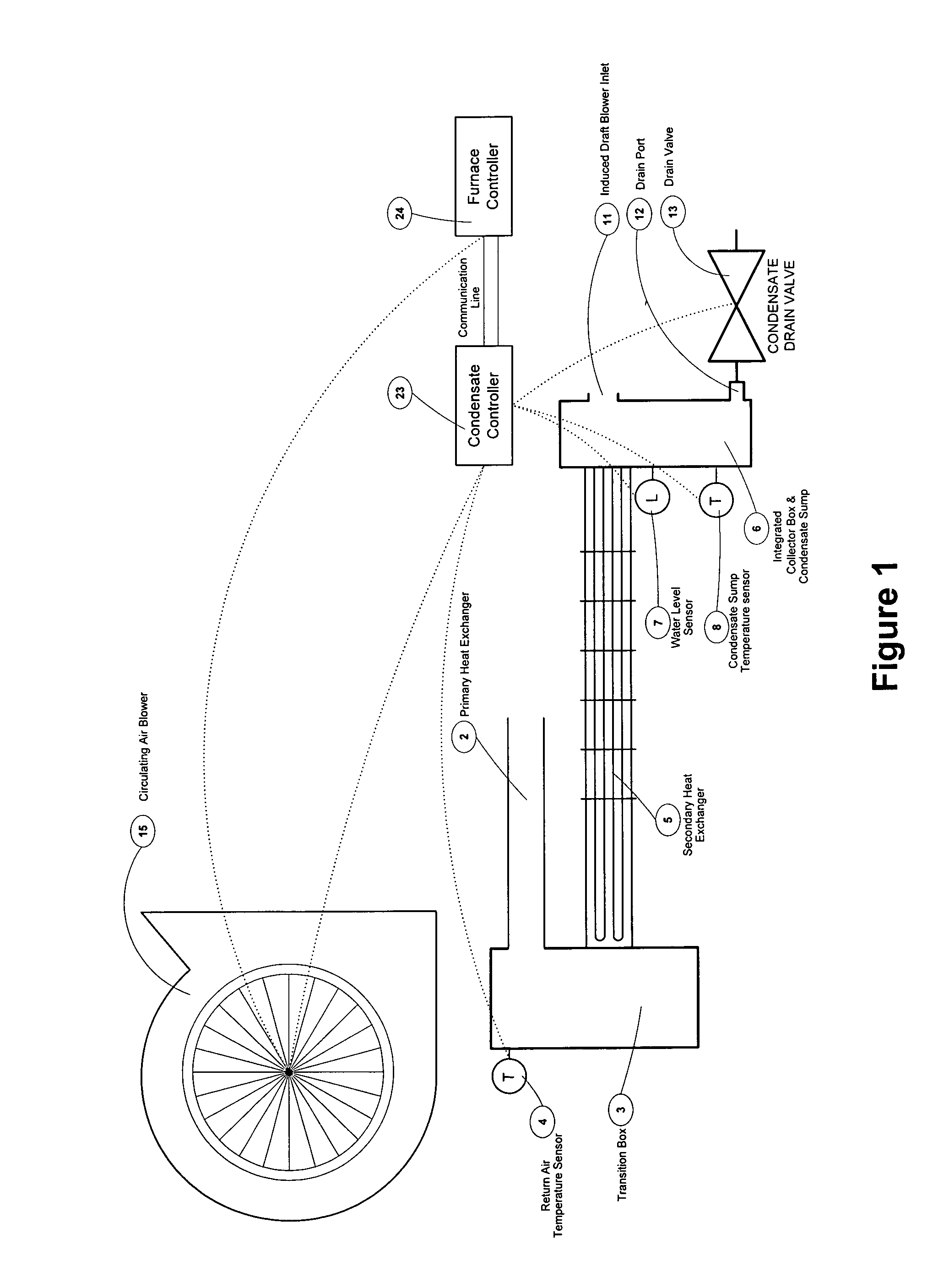
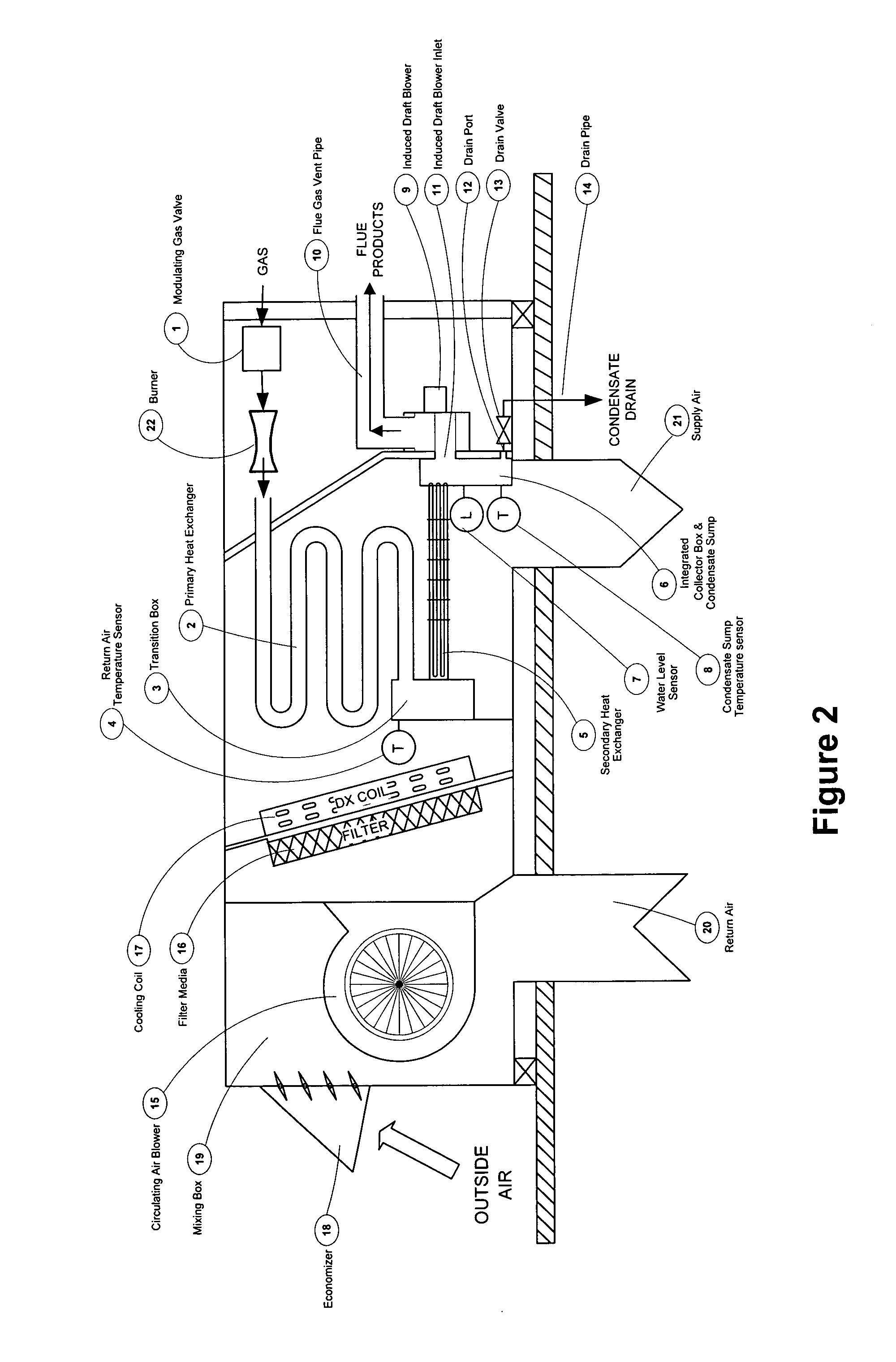
[0017]In some embodiments of a condensate management system according to this invention, sump 6, which can be a deep condensate sump, collects a desired or specified volume of water, for example about one gallon or two gallons, in a vessel or container sufficiently deep to overcome a negative pressure in primary heat exchanger 2 and / or secondary heat exchanger 5. For example the vessel or container forming sump 6 can be about six inches deep or can have any other suitable dimension and / or shape. In some embodiments of this invention, such as shown in FIGS. 1 and 2, sump 6 is integrated with a collection box for collecting condensate formed on primary heat exchanger 2 and / or secondary heat exchanger 5. In other embodiments of this invention, sump 6 is not integrated with the collection box but rather is an independent vessel or container, for example that is not integrated into or with a collection box for the overall heat exchanger.

[0018]Condensate fluid can flow into sump 6, for ex...


PUM


Abstract

A method for controlling an efficiency and / or a wet / dry transition area of a condensing furnace heat exchanger section. A temperature can be sensed in an air stream entering the heat exchanger section, to sense an incoming air temperature of the air stream entering the heat exchanger section. A relationship can be established between the incoming air temperature and an air / fuel mixture to be supplied to a burner. The air / fuel mixture can be adjusted to enhance the efficiency and / or to minimize or reduce unwanted condensation within the heat exchanger section.

Description

BACKGROUND OF THE INVENTION[0001]1. Field of the Invention[0002]This invention relates to a method for controlling an efficiency of a condensing furnace heat exchanger by sensing and controlling operating parameters to minimize or reduce unwanted condensation, particularly from condensate-corrosive surfaces of the heat exchanger section.[0003]2. Discussion of Related Art[0004]It is known in the HVAC industry to design high-efficiency, gas-fired forced air furnaces to optimize fuel usage in residential and commercial heating applications. Conventional mid-efficiency, non-condensing furnaces are limited to steady state efficiencies of 83% or less to limit corrosion in flue passages which causes premature failure of heat exchanger surfaces and other components in the flue stream. Conventional high-efficiency condensing furnaces can obtain efficiencies over 98% and are designed to produce and manage condensate from the combustion products to protect heat exchanger components and remove ...

Claims


Application Information

Patent Timeline
Patent Type & Authority Applications(United States)
IPC IPC(8): F24H3/02G05D23/00F24H9/20F23N5/00F23N1/02
CPCF23N1/02F23N5/00G05D22/02F24D2200/046G05D27/02F24H3/087F24H9/2085G05D23/19Y10T137/0318F24H15/33F24H15/246F24H15/31F24H15/395F24H15/345F24H15/20F24H15/204F24H15/36F24H15/258
Inventor MAIELLO, DENNIS R.GAMBIANA, DENNIS S.
Owner HVAC MODULATION TECH
Why Eureka
Try Eureka