Measurement apparatus

a technology of measurement apparatus and measuring rod, which is applied in the field of measurement apparatus, can solve problems such as difficult detection, and achieve the effect of simple configuration

Active Publication Date: 2013-05-02
OMRON HEALTHCARE CO LTD
View PDF2 Cites 19 Cited by
  • Summary
  • Abstract
  • Description
  • Claims
  • Application Information

AI Technical Summary

Benefits of technology

[0008]Having been achieved in light of the stated problem, it is an object of the present invention to provide a measurement apparatus capable of evaluating the likelihood of a predetermined pathologic change in a vascular pathway, such as an abdominal aortic aneurysm, using a simple configuration that can be implemented during a health checkup or the like.
[0014]According to this invention, the likelihood of a predetermined pathologic change in a vascular pathway, such as an abdominal aortic aneurysm, can be evaluated accurately, using a simple configuration.

Problems solved by technology

Accordingly, from the standpoint of time and costs, there is a problem in that it is difficult to detect, through health checkups or the like, individuals affected by aortic aneurysms from among many individuals.

Method used


Image

  • Measurement apparatus
  • Measurement apparatus
  • Measurement apparatus

Examples


second embodiment

Apparatus Configuration

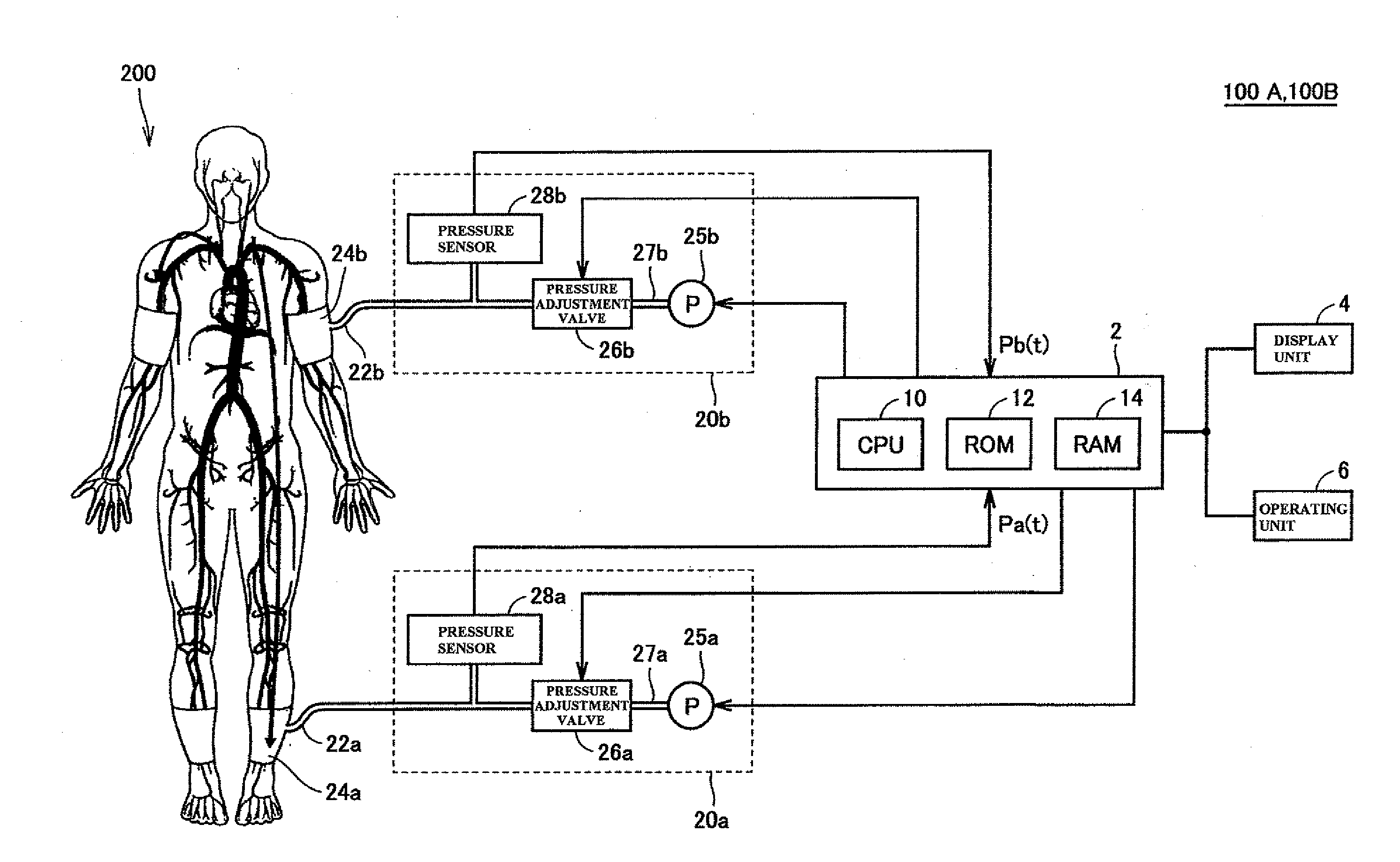
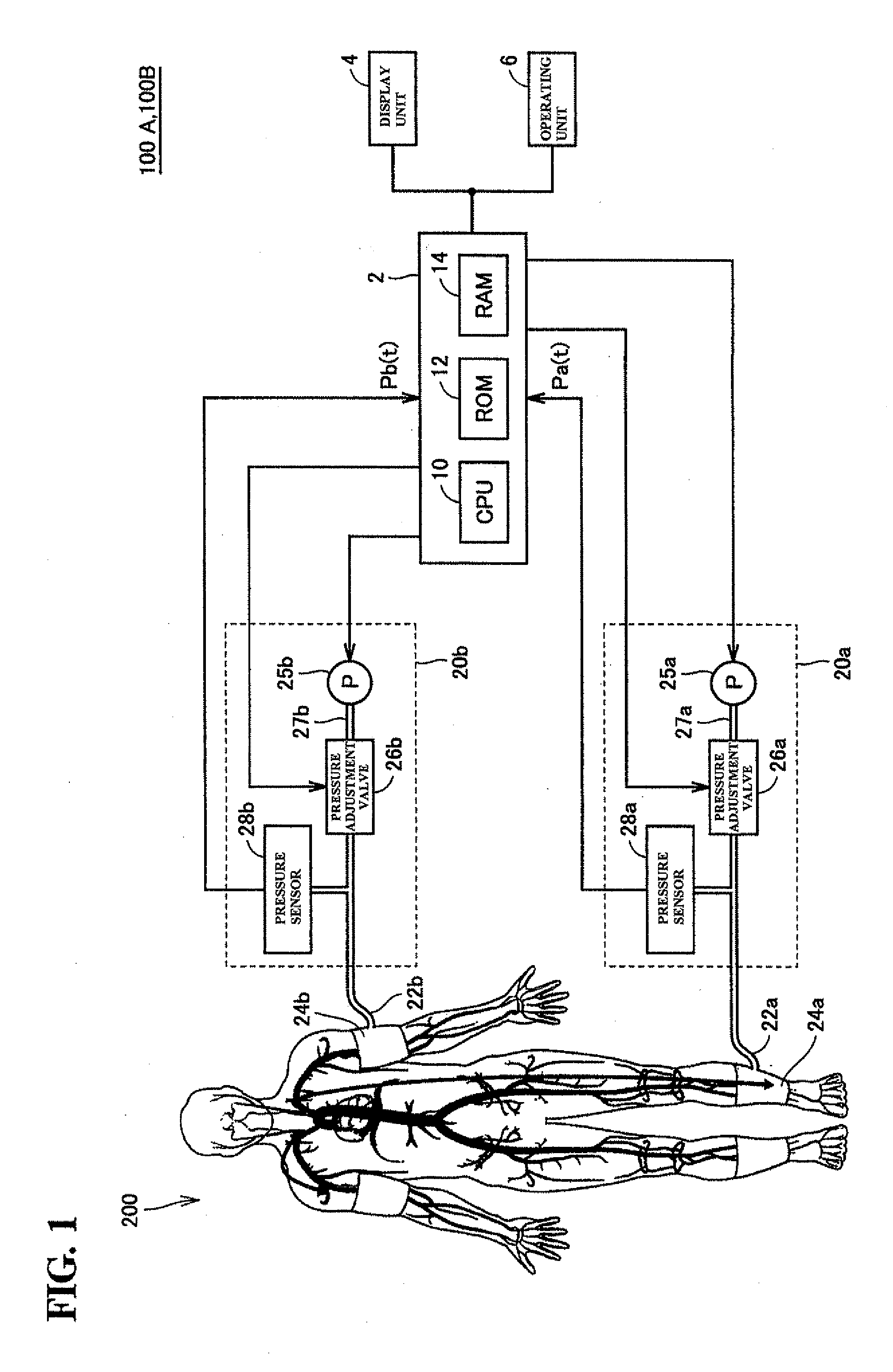
[0097]The apparatus configuration of a measurement apparatus 100B according to a second embodiment is the same as the configuration of the measurement apparatus 100A illustrated in FIG. 1.

[0098]Function Block Diagram

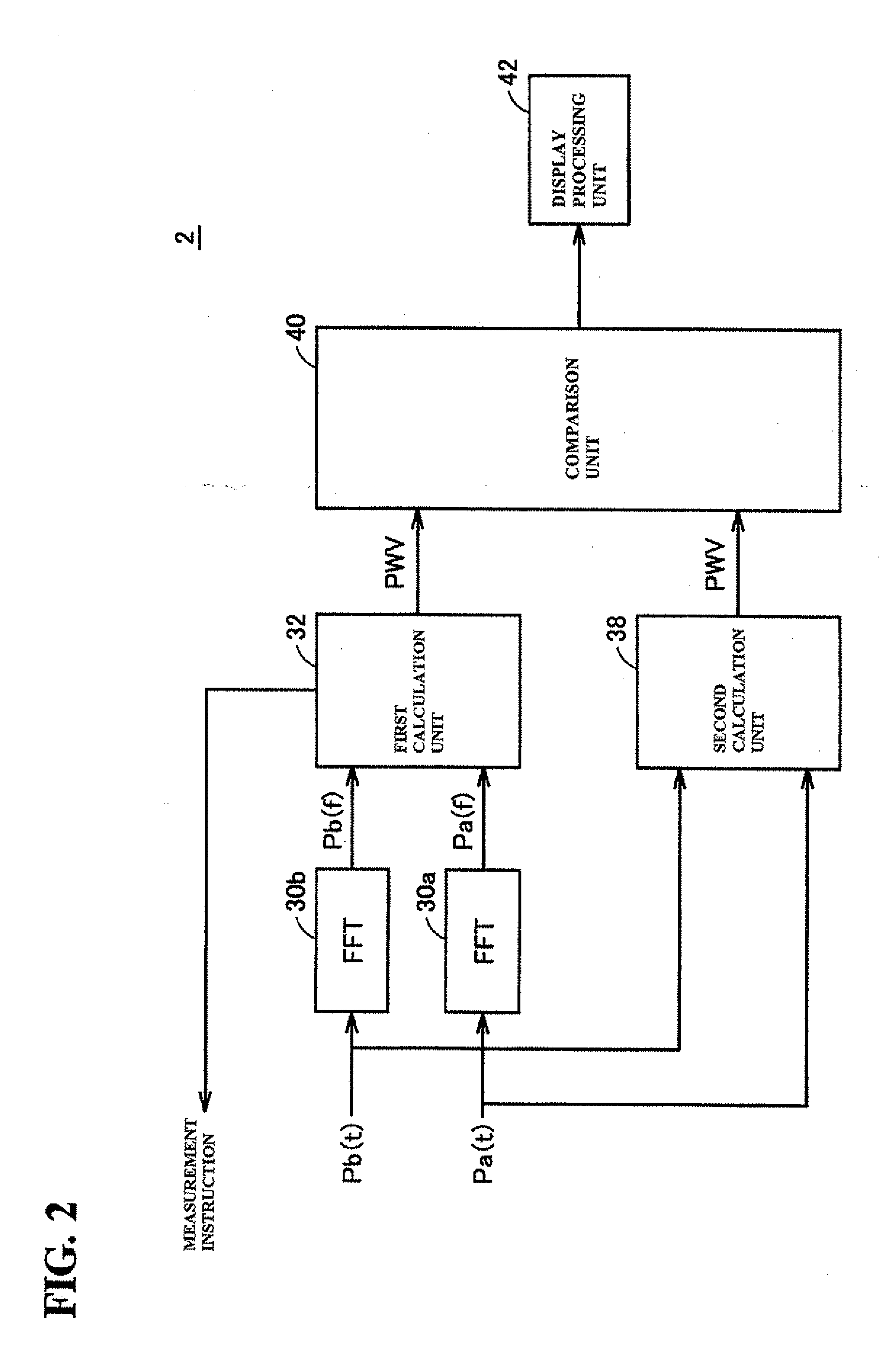
[0099]FIG. 6 is a function block diagram schematically illustrating functions executed by the control unit 2 of the measurement apparatus 100B.

[0100]As shown in FIG. 6, the control unit 2 implements the frequency transform units (PFT) 30a and 30b, the first calculation unit 32, a third calculation unit 39, the comparison unit 40, and the display processing unit 42. In other words, the control unit 2 of the measurement apparatus 100B implements the third calculation unit 39 instead of the second calculation unit 38 implemented by the control unit 2 of the measurement apparatus 100A; the other elements are the same as in the control unit 2 of the measurement apparatus 100A. The differences will be described hereinafter.

[0101]Calculation of Pulse Wave...


PUM


Abstract

A first calculation unit receives phase characteristics Pa(f) and Pb(f) outputted from frequency transform units, calculates a propagation time difference based on a phase difference between the two phase characteristics in a high-frequency component thereof, and calculates a pulse wave velocity by dividing a difference in the distances of vascular pathways from the heart to respective measurement areas. Meanwhile, a second calculation unit calculates a pulse wave velocity by dividing the stated difference in the distances by a appearance time difference at a predetermined position in respective pulse waveforms obtained by rendering the measurement signals Pa(t) and Pb(t) on a time axis. A comparison unit compares the pulse wave velocities, and in the case where the ratio thereof is outside a predetermined range, an evaluation result indicating that it is possible that a predetermined pathologic change is present in the vascular pathway is outputted to a display processing unit.

Description

[0001]This is continuation of application Serial No. PCT / JP2011 / 066340 filed Jul. 19, 2011, the contents of which are incorporated herein by reference.BACKGROUND OF THE INVENTION[0002]1. Field of the Invention[0003]This invention relates to measurement apparatuses, and particularly relates to measurement apparatuses for evaluating the likelihood of a predetermined pathologic change in a vascular pathway.[0004]2. Description of the Background Art[0005]Aortic aneurysm can be given as an example of a predetermined pathologic change in a vascular pathway. An aortic aneurysm in the abdominal area in particular has no early symptoms, and unless unintentionally discovered during an MRI (magnetic resonance imaging system), a CT (computed tomography) scan, or the like, is often discovered just before rupture, during an abdominal surge or the like. It is therefore desirable to detect such a condition early through a casual examination, such as during a health checkup.[0006]JP H5-23335A disclo...

Claims


Application Information

Patent Timeline
Patent Type & Authority Applications(United States)
IPC IPC(8): A61B5/024A61B5/00
CPCA61B5/02014A61B5/0285A61B5/6824A61B5/7246A61B5/02438A61B5/02444A61B5/7225A61B5/6829A61B5/0295
Inventor SATO, HIRONORIMORI, NAOKIHASHIMOTO, TOMOKOOGURA, TOSHIHIKOTAKAMATSU, SHOZOUTSUNO, HIDEOKICHIKAWA, KIMIHIKOITO, HIROFUMI
Owner OMRON HEALTHCARE CO LTD
Why Eureka
Try Eureka