Real time CSF flow measurement system & method

Inactive Publication Date: 2013-05-02
SHUNTCHECK
View PDF17 Cites 19 Cited by
  • Summary
  • Abstract
  • Description
  • Claims
  • Application Information

AI Technical Summary

Benefits of technology

[0010]An apparatus for determining cerebrospinal fluid (CSF) flow rate in an implanted CSF shunt is disclosed. The apparatus comprises: a pad that is placed against the skin of a patient over the location of the CSF shunt wherein the said pad comprises: a first plurality of temperature sensors (e.g., thermistors) that are aligned in a transverse direction with respect to the CSF shunt and wherein one of the first plurality of temperature sensors is aligned with the CSF shunt; and a second plurality of temperature sensors that are aligned in a transverse direction with respect to the CSF shunt, downstream of the first plurality of temperature sensors, and wherein one of the second plurality of temperature sensors is aligned with the CSF shunt

Problems solved by technology

It can lead to neurodegeneration and death if untreated.
The usual clinical manifestations of shunt failure (headaches, vomiting) are non-specific, making shunt obstruction difficult to differentiate from less serious illnesses, particularly in pediatric patients in whom three false alarms are seen for every true malfunction [4].
Physical examination, including pumping of the shunt reservoir, is unreliable [21].
CT (computed tomography)

Method used


Image

  • Real time CSF flow measurement system & method
  • Real time CSF flow measurement system & method
  • Real time CSF flow measurement system & method

Examples


Embodiment Construction

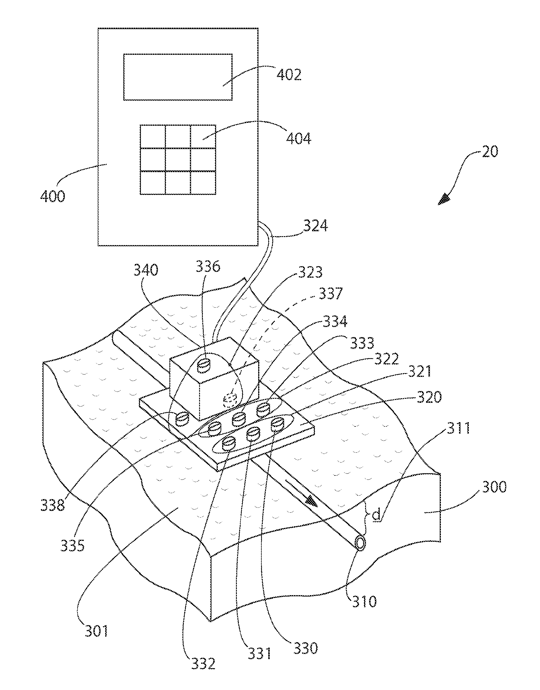
[0032]The present invention 20 overcomes the deficiencies of the prior art by providing a system of thermosensors strategically placed on the skin surface and a cooling system. In particular, the present invention 20 provides a CSF real time, thermal flow measurement method and system which are capable of compensating for changing thermal properties of the skin and which are also capable of compensating for skin thickness (e.g., depth of shunt tubing implantation). The present invention 20 also provides a method of CSF real time, thermal flow measurement system which is based on three sets (arrays) of sensors and a cooling device. In addition, the present invention 20 also provides a method of shunt valve adjustment based on information provided by the CSF flow measuring system. Moreover, the present invention 20 provides a method of ICP assessment based on information provided by the CSF flow measuring system and settings of the adjustable shunt valve.

[0033]This invention 20 (see F...


PUM


Abstract

A system for measuring quantitative CSF flow in shunt tubing implanted under the skin. The system includes an array of thermosensors clustered in three sections, cooling device, placed on the skin surface and an associated data acquisition and analysis device. Two sensor sections are placed over the shunt on the skin and measure real time temperature responses related to CSF movement. One array placed adjacent the cooling device collects data on thermal properties of skin including skin thermal condictivity, specific heat, diffusivity, perfusion, and thermal inertia. The method involves assessing thermal properties of skin and measuring CSF flow in shunt tubing. The method is useful for shunt patency assessment, CSF valve adjustment procedures and CSF flow measurements related to CSF over drainage. Alternatively, only one section of sensors need be used when determining relative CSF flow, without the need to determine thermal skin properties and by applying the cooling device continuously.

Description

CROSS-REFERENCE TO RELATED APPLICATIONS[0001]This PCT application claims the benefit under 35 U.S.C. §119(e) of Provisional Application Ser. No. 61 / 396,436 filed on May 28, 2010 entitled REAL TIME CSF FLOW MEASUREMENT SYSTEM AND METHOD and whose entire disclosure is incorporated by reference herein.BACKGROUND OF THE INVENTION[0002]1. Field of Invention[0003]This present invention generally relates to cerebrospinal fluid (CSF) shunts and, more particular, to a device and method for testing for the presence, absence and / or rate of flow in the shunt tubing implanted under the skin.[0004]2. Description of Related Art[0005]Approximately 69,000 people are diagnosed with hydrocephalus each year in the United States [1]. There are approximately 300,000 shunted hydrocephalus patients in the US [3][4].[0006]The one-year shunt failure rate of shunts is approximately 40% [15, 16], and the mean period to failure is typically only 5-10 years [17]. Obstruction of the ventricular catheter is overwh...

Claims


Application Information

Patent Timeline
IPC IPC(8): A61B5/03G01F1/684
CPCA61B5/01A61B5/031A61M5/168A61M27/006A61B5/032G01F1/684A61M5/16836
Inventor SWOBODA, MAREKHOCHMAN, MATIAS GABRIELMATTIUCCI, MARK EVANFRITZ, FREDERICK J.
Owner SHUNTCHECK
Why Eureka
Try Eureka