Memory alloy-actuated apparatus and methods for making and using the same

Active Publication Date: 2013-05-09
AUTOSPLICE SYST
View PDF6 Cites 17 Cited by
  • Summary
  • Abstract
  • Description
  • Claims
  • Application Information

AI Technical Summary

Benefits of technology

[0012]The aforementioned needs are satisfied herein by providing improv

Problems solved by technology

A common limitation with regards to electromechanical solenoids (particularly those that are used in small or portable consumer applications) is the fact that the actuating current is often generated via a series of batteries.
These solenoid actuators generally have comparatively large power requirements, and are often inefficient due to, inter alia, the internal resistance associated with the application of an electric current across the solenoid coils.
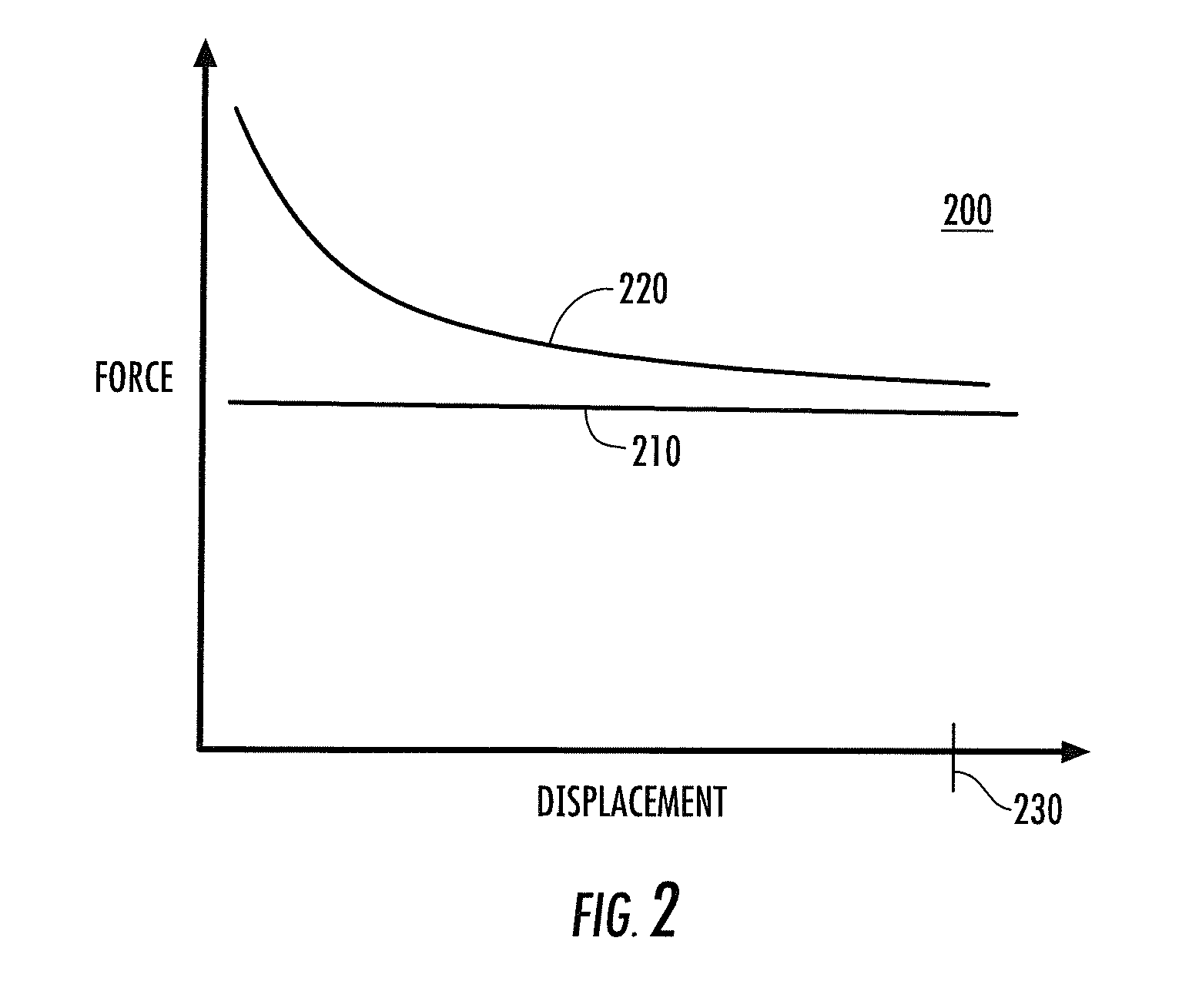
In addition, electromechanical solenoids typically do not output a constant applied force as a function of actuation distance.
This is problematic, particularly in low power applications, in that electromechanical solenoid designs are generally “over-designed” for much of the actuating stroke length of the solenoid, i.e. more stroke force then is necessary is present throughout much of the stroke length of the solenoid, thereby decreasing the efficiency of the de

Method used


Image

  • Memory alloy-actuated apparatus and methods for making and using the same
  • Memory alloy-actuated apparatus and methods for making and using the same
  • Memory alloy-actuated apparatus and methods for making and using the same

Examples


Embodiment Construction

[0039]As used herein, the term “filament” refers to any substantially elongate body, form, strand, or collection of the foregoing, including without limitation drawn, extruded or stranded wires or fibers, whether metallic or otherwise.

[0040]As used herein, the term “shape memory alloy” or “SMA” shall be understood to include, but not be limited to, any metal that is capable of “remembering” or substantially reassuming a previous geometry. For example, after it is deformed, it can either substantially regain its original geometry by itself during e.g., heating (i.e., the “one-way effect”) or, at higher ambient temperatures, simply during unloading (so-called “pseudo-elasticity”). Some examples of shape memory alloys include nickel-titanium (“NiTi” or “Nitinol”) alloys and copper-zinc-aluminum alloys.

Overview

[0041]In one aspect, the present disclosure provides an actuator apparatus having many advantages with respect to common prior art approaches, such as those previously described h...


PUM


Abstract

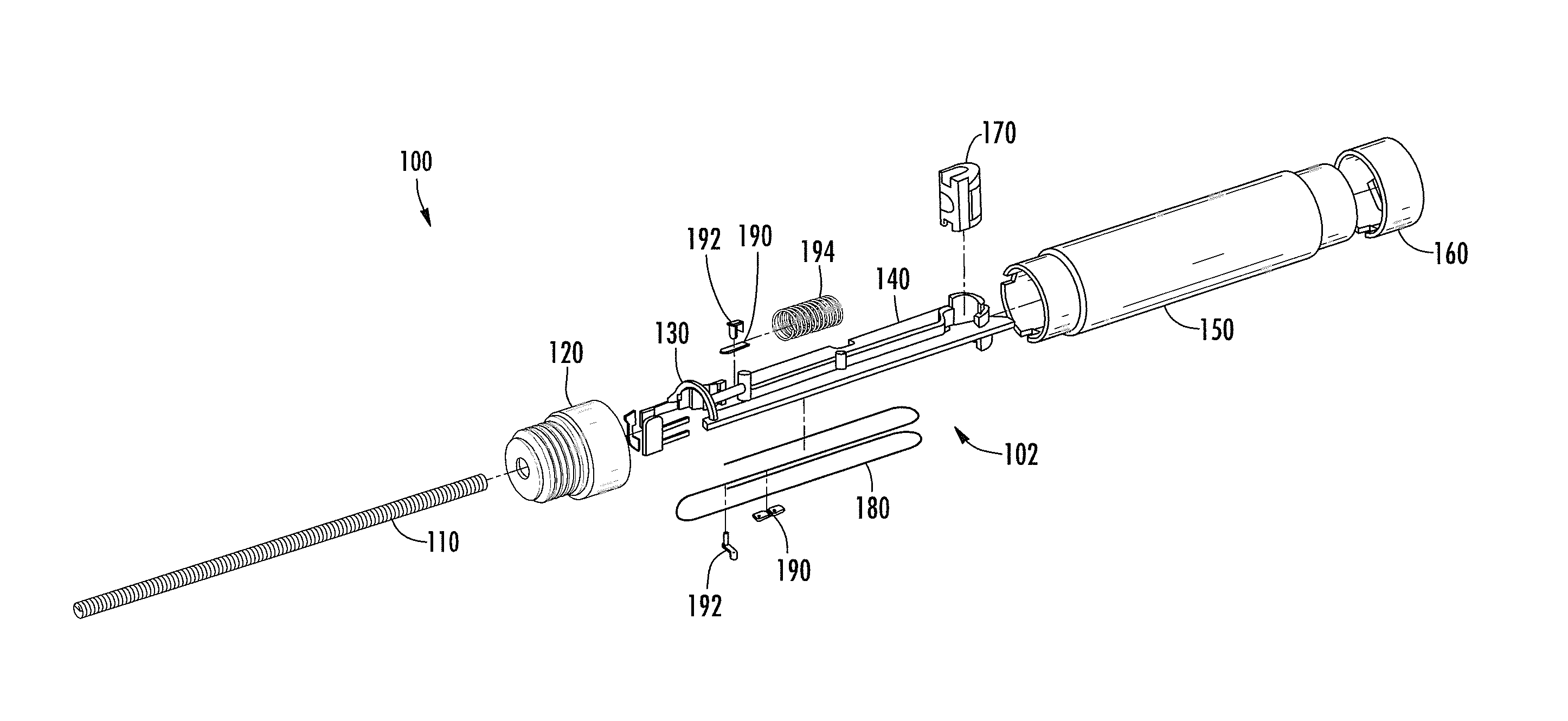
Improved actuator apparatus and methodologies for manufacturing and using the same. In one exemplary embodiment, the actuator apparatus includes an SMA filament that: (1) minimizes size and increases stroke length via a serpentine-like routing of the SMA filament within the device itself; (2) reduces power consumption as a result of a relatively flat stroke force as a function of stroke displacement operating profile; (3) enables the actuator assembly to remain in a fully actuated state, at a consistent stroke force, for longer periods of time; and (4) is also fully reversible so as to be capable of use in both push-based and pull-based actuator applications. Methods of operation and manufacturing associated with the aforementioned actuator apparatus are also disclosed.

Description

RELATED APPLICATIONS[0001]This application claims priority to co-owned and co-pending U.S. provisional patent application Ser. No. 61 / 551,739 filed Oct. 26, 2011 of the same title, the contents of which are incorporated herein by reference in their entirety.[0002]This application is also related to co-owned and co-pending U.S. patent application Ser. No. 12 / 539,521 filed Aug. 11, 2009 and entitled “Multi-Stable Actuation Apparatus and Methods for Making and Using the Same” which claims priority to U.S. provisional patent application Ser. No. 61 / 189,148 filed Aug. 14, 2008 of the same title and to U.S. provisional patent application Ser. No. 61 / 206,883 filed Feb. 4, 2009 and entitled “Memory Alloy-Actuated Apparatus and Methods for Making and Using the Same”, each of the foregoing being incorporated herein by reference in its entirety. This application is also related to co-owned and co-pending U.S. patent application Ser. No. 13 / 149,508 filed May 31, 2011 and entitled “Power-Efficie...

Claims


Application Information

Patent Timeline
IPC IPC(8): F03G7/06
CPCF03G7/065
Inventor FOSHANSKY, LEONIDBOGURSKY, ROBERT
Owner AUTOSPLICE SYST
Why Eureka
Try Eureka