

Sensor element, force detecting device, and robot
a technology of force detection and sensor element, which is applied in the direction of force/torque/work measurement apparatus, instruments, tension measurement, etc., can solve the problem of difficulty in reducing the size of the force detecting device, and achieve the effect of high reliability
- Summary
- Abstract
- Description
- Claims
- Application Information
AI Technical Summary
Benefits of technology
Problems solved by technology
Method used
Image

Examples
first embodiment
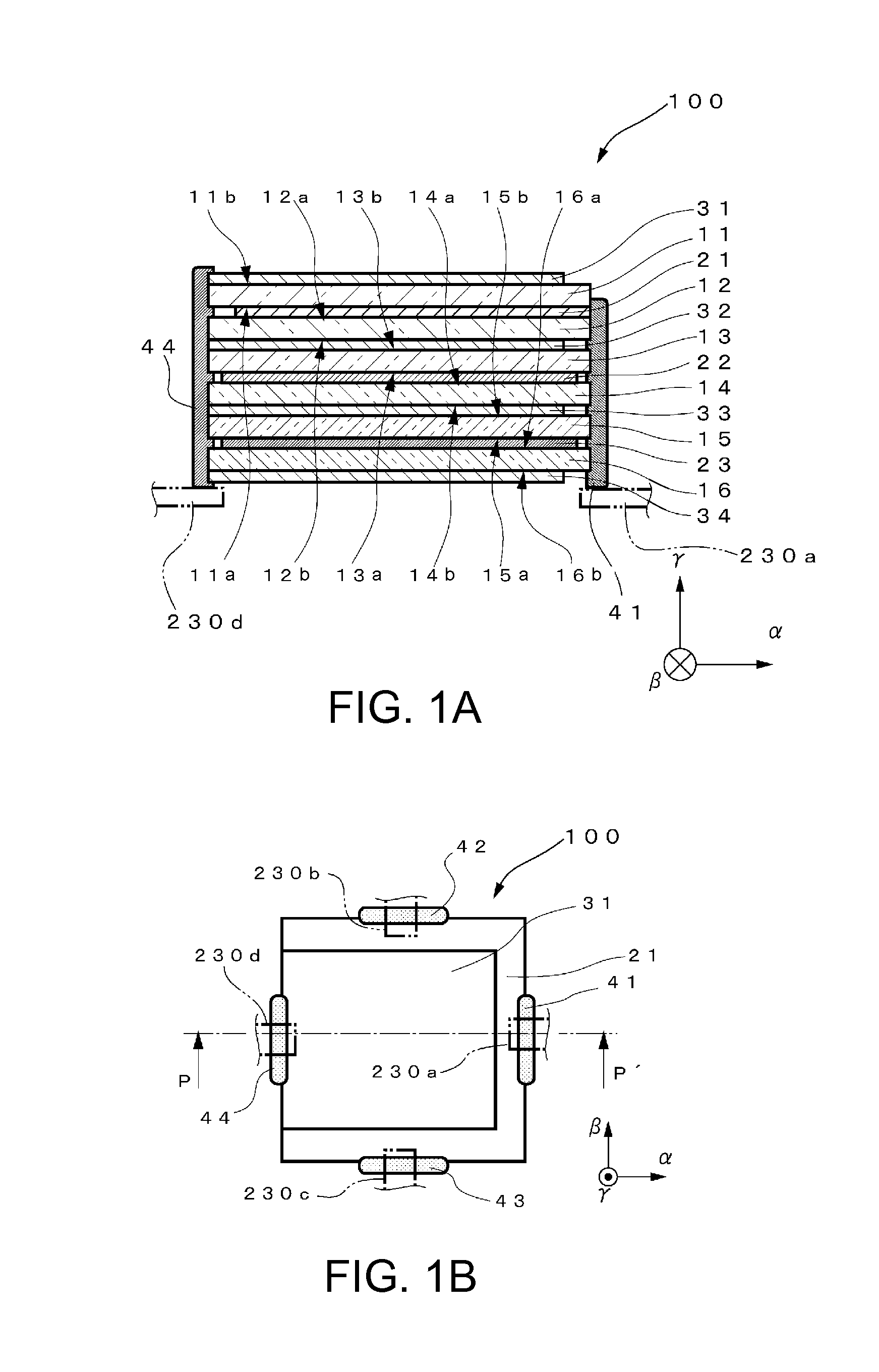
[0052]FIG. 1A is a sectional view showing a sensor element according to a first embodiment. FIG. 1B is a plan view of the sensor element.
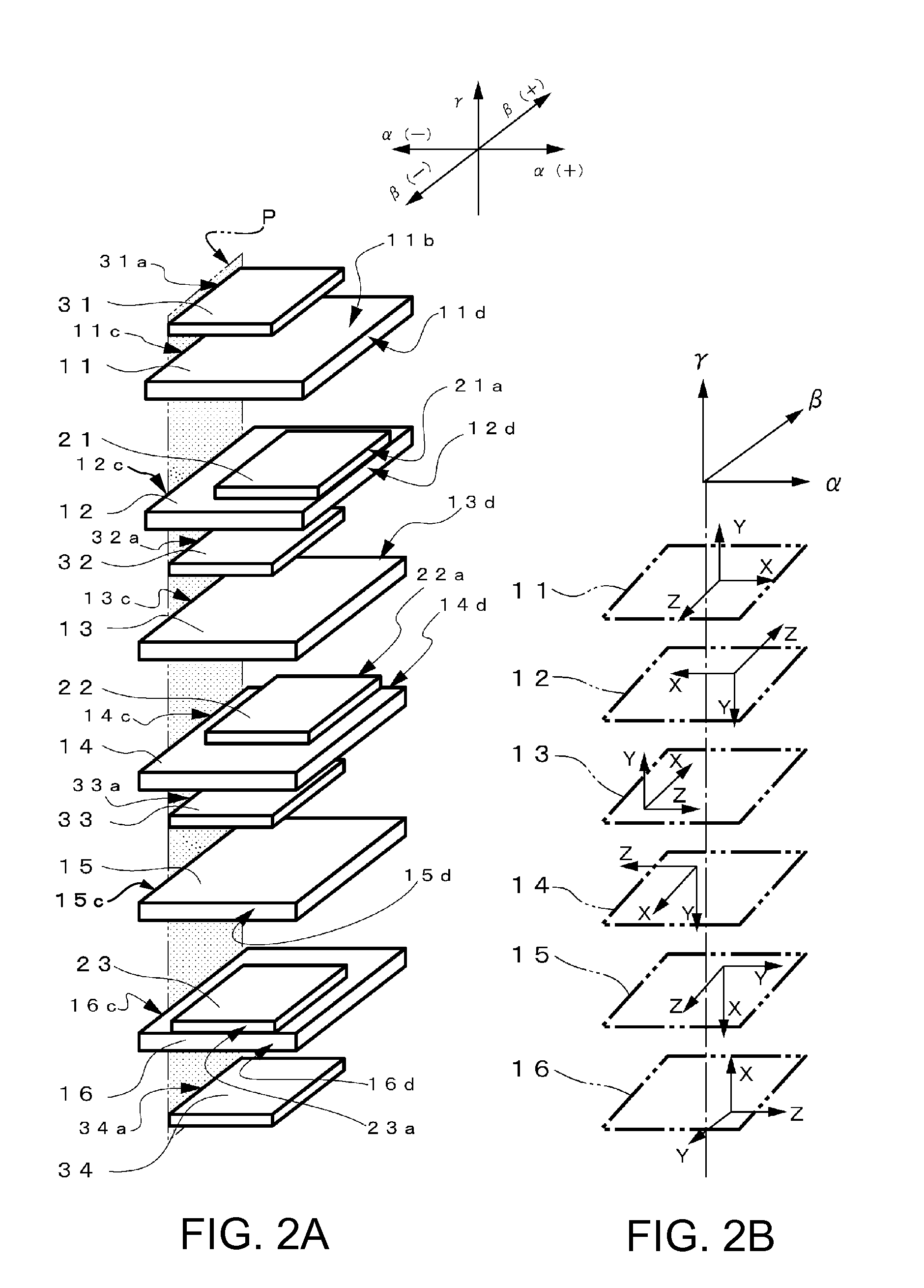
[0053]As shown in FIG. 1A of a cross section in a P-P′ portion shown in FIG. 1B, in a sensor element 100 according to this embodiment, quartz substrates functioning as piezoelectric substrates, i.e., a first quartz substrate 11 and a second quartz substrate 12 functioning as a first piezoelectric substrate, a third quartz substrate 13 and a fourth quartz substrate 14 functioning as a second piezoelectric substrate, and a fifth quartz substrate 15 and a sixth quartz substrate 16 functioning as a third piezoelectric substrate are laminated in the γ axis direction.
[0054]A first detection electrode 21 functioning as a first electrode is provided on one principal plane 11a side of the first quartz substrate 11. A ground electrode (hereinafter referred to as GND electrode) 31 functioning as a second electrode is provided on the other principal plane 11b ...
second embodiment
[0068]FIGS. 4A and 4B show a sensor element according to a second embodiment. Compared with the sensor element 100 according to the first embodiment, a sensor element 110 according to the second embodiment is different in the shapes of the quartz substrates 11, 12, 13, and 14, the detection electrodes 21, 22, and 23, and the GND electrodes 31, 32, 33, and34. The other components are substantially the same. Therefore, the same components are denoted by the same reference numerals and signs and detailed explanation of the components is omitted.
[0069]FIG. 4A is a plan view of a quartz substrate 1A functioning as a piezoelectric substrate that forms the sensor element 110 according to the second embodiment. FIG. 4B is a plan view of a detection electrode 2A functioning as a first electrode and a GND electrode 3A functioning as a second electrode. On the quartz substrate 1A shown in FIG. 4A, a substrate base section 1Aa is formed. Substrate projecting sections 1Ab are formed on the exter...
third embodiment
[0075]FIG. 6 is a sectional view of a sensor element according to a third embodiment. In the sensor element 100 according to the first embodiment, each of the forces in the α, β, and γ axis directions is generated by using the two quartz substrates functioning as the piezoelectric substrates, i.e., the forces are generated by using the six quartz substrates. On the other hand, in a sensor element 120 according to the third embodiment, each of the forces in the α, β, and γ axis directions is generated by using one quartz substrate, i.e., the forces are generated by using the three quartz substrates. Therefore, in the explanation of the sensor element 120 according to the third embodiment, explanation of components that are the same as those of the sensor element 100 according to the first embodiment is omitted. The same components are denoted by the same reference numerals and signs.
[0076]In the sensor element 120 shown in FIG. 6, a first quartz substrate 11B functioning as a first p...
PUM
 Abstract
Description
Claims
Application Information