Magnetic memory element, magnetic memory and manufacturing method of the same

a technology of magnetic memory and manufacturing method, which is applied in the direction of solid-state devices, semiconductor devices, instruments, etc., can solve the problems of difficult technique of patent literature 2 and achieve the effect of stably holding information

Active Publication Date: 2013-05-09
NEC CORP
View PDF2 Cites 12 Cited by
  • Summary
  • Abstract
  • Description
  • Claims
  • Application Information

AI Technical Summary

Benefits of technology

[0022]In a MRAM (a domain wall motion MRAM) to which current induced domain wall motion is applied, information is stored corresponding to a position of a domain wall. Therefore, in order to stably hold information, it is necessary to provide a mechanism in which the domain wall is stably trapped in a certain position during a non-operation time. The patent literature 2 discloses a method using a step as a structure for stably trapping the domain wall in a racetrack memory. Here, it is assumed that a method using this step is the trapping mechanism (a pinning site) for the domain wall of the domain wall motion MRAM (the perpendicular magnetization domain wall motion MRAM) using ferromagnetic material with perpendicular magnetic anisotropy. In this case, a film thickness of a perpendicular magnetization film is approximately several nano-meters, and a domain wall width (a thickness of the domain wall) is approximately 10 nano-meters. Therefore, it is preferable that a height of the step is approximately several nano-meters, and a length of the step in a lateral direction (a direction of the thickness of the domain wall) is approximately 10 nano-meters or less. In addition, it is preferable that the height of the step is controllable arbitrarily. When the inventor of the present invention has tried to form the step by using the manufacturing method disclosed in the patent literature 2, it has been found that arbitrary control of the height of the step at the several nano-meter level is very difficult, a taper angle of the step becomes relatively gradual, and the length becomes 10 nano-meters or more. That is, in the recent MRAM in which the miniaturization has been developing, it has been found that it is very difficult for the technique of the patent literature 2 to excellently act as the trapping mechanism of the domain wall from a practical standpoint.

Problems solved by technology

That is, in the recent MRAM in which the miniaturization has been developing, it has been found that it is very difficult for the technique of the patent literature 2 to excellently act as the trapping mechanism of the domain wall from a practical standpoint.

Method used


Image

  • Magnetic memory element, magnetic memory and manufacturing method of the same
  • Magnetic memory element, magnetic memory and manufacturing method of the same
  • Magnetic memory element, magnetic memory and manufacturing method of the same

Examples


first exemplary embodiment

1. Structure

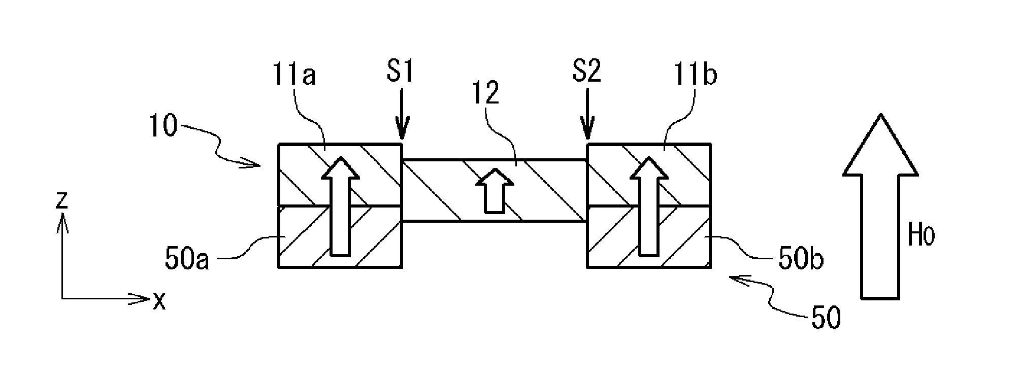
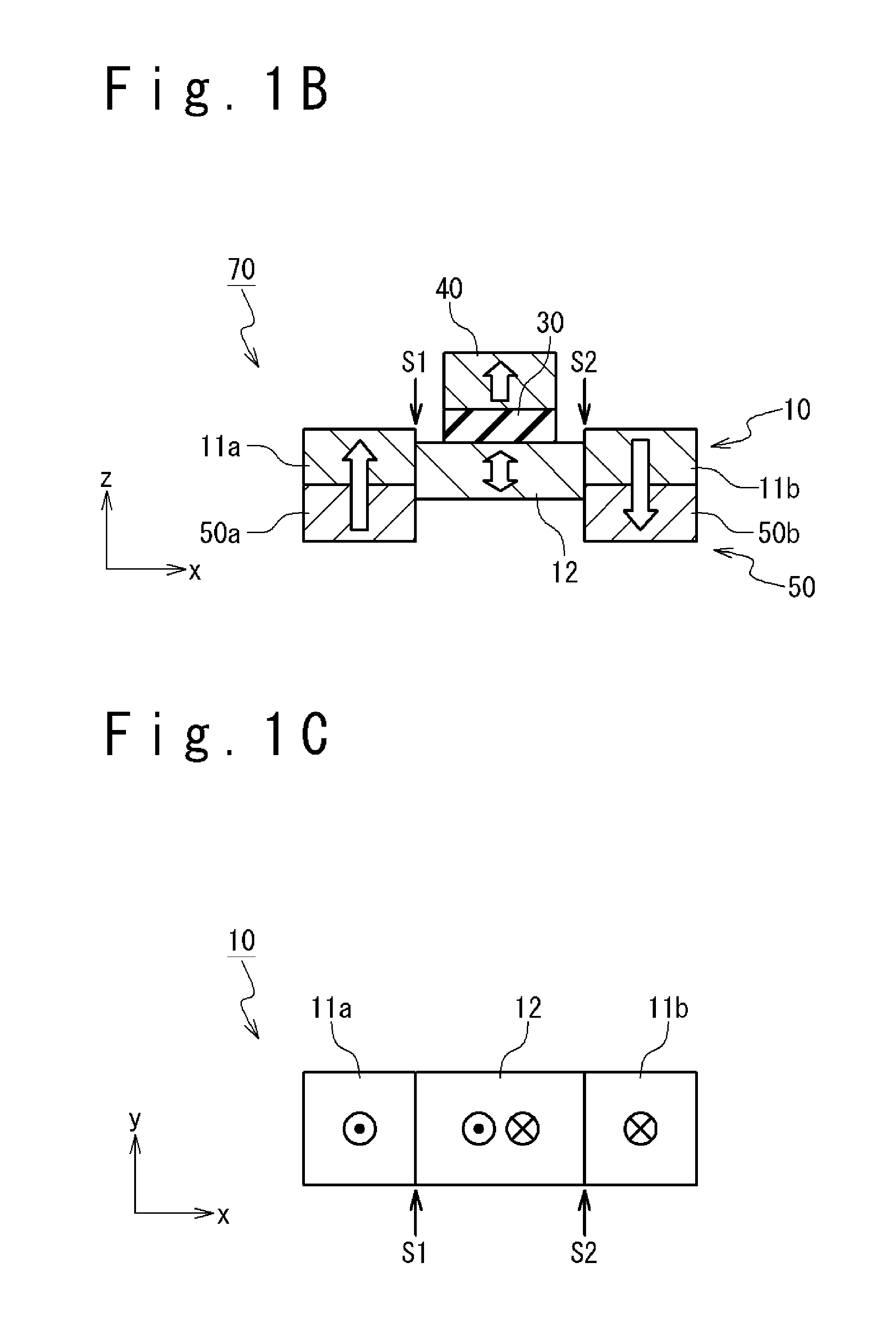
[0076]FIGS. 1A, 1B and 1C schematically show a typical structure of a main portion of a magnetic memory element 70 according to a first exemplary embodiment of the present invention. FIGS. 1A, 1B and 1C show a perspective view, an x-z sectional view and an x-y plan view, respectively. Here, it is assumed that, in the x-y-z coordinate system shown in the drawings, the z axis is a direction perpendicular to the substrate, and the x axis and the y axis are directions parallel to the surface of the substrate (substrate surface). The magnetic memory element 70 includes a first magnetization free layer 10, a non-magnetic layer 30, a reference layer 40 and a step formation layer 50.

[0077]Specifically, FIG. 1C is the plan view schematically showing a structure of the first magnetization free layer 10. The first magnetization free layer 10 is composed of ferromagnetic material with perpendicular magnetic anisotropy. Further, the first magnetization free layer 10 included three re...

first modification example

11-1. First Modification Example

[0124]FIGS. 10A and 10B schematically show a structure of the first modification example of the magnetic memory element according to the first exemplary embodiment of the present invention. FIG. 10A shows the perspective view and FIG. 10B shows the x-z sectional view. The first modification example relates to the step shape.

[0125]In the present exemplary embodiment, in the first magnetization free region 10, the first step S1 is provided at the boundary between the first magnetization fixed region 11a and magnetization free region 12, and the second step S2 is provided at the boundary between the second magnetization fixed region 11b and the magnetization free region 12. In the example shown in FIGS. 1A to 1C, the height of the magnetization free region 12 is lower than the height of the first magnetization fixed region 11a and the height of the second magnetization fixed region 11b. However, the shape of the step is arbitrary. For example, as shown i...

second modification example

11-2. Second Modification Example

[0127]FIG. 11A schematically show structures of the second modification example of the magnetic memory element 70 according to the first exemplary embodiment of the present invention. FIG. 11A shows the perspective view and FIG. 11B shows the x-z sectional view. The second modification example relates to the material of the step formation layer 50, the initialization method, and the method of fixing the magnetization of the first magnetization fixed region 11a and the second magnetization fixed region 11b.

[0128]In the present exemplary embodiment, the first magnetization free layer 10 includes: the first magnetization fixed region 11a, the second magnetization fixed region 11b and the magnetization free region 12, and the magnetization of the first magnetization fixed region 11a and the magnetization of the second magnetization fixed region 11b are fixed such that they are anti-parallel to each other. Therefore, the initialization process is require...


PUM

PropertyMeasurementUnit
currentaaaaaaaaaa
currentaaaaaaaaaa
thicknessaaaaaaaaaa

Abstract

A magnetic memory element includes: a first magnetization free layer configured to be composed of ferromagnetic material with perpendicular magnetic anisotropy; a reference layer configured to be provided near the first magnetization free layer; a non-magnetic layer configured to be provided adjacent to the reference layer; and a step formation layer configured to be provided under the first magnetization free layer. The first magnetization free layer includes: a first magnetization fixed region of which magnetization is fixed, a second magnetization fixed region of which magnetization is fixed, and a magnetization free region configured to be connected with the first magnetization fixed region and the second magnetization fixed region. The first magnetization free layer has at least one of a step, a groove and a protrusion inside.

Description

TECHNICAL FIELD[0001]The present invention relates to a magnetic memory element, a magnetic memory and a manufacturing method of the same. Particularly, the present invention relates to a magnetic memory element, a magnetic memory and a manufacturing method of the same, to which domain wall motion is applied.BACKGROUND ART[0002]A magnetic memory or a magnetic random access memory (MRAM) is a nonvolatile memory capable of a high-speed operation and rewriting an infinite number of times. Therefore, some types of MRAMs have been put into practical use, and some types of MRAMs have been developing to improve their general versatility. In the MRAM, magnetic material is used for a memory element, and data is stored in the memory element as a magnetization direction of the magnetic material. Some methods for switching the magnetization direction of the magnetic material are proposed. Those methods have in common with usage of a current. To put the MRAM into practical use, it is important t...

Claims


Application Information

Patent Timeline
Patent Type & Authority Applications(United States)
IPC IPC(8): H01L43/02H01L43/12
CPCH01L27/228H01L43/08G11C11/161H01L43/02H01L43/12H10B61/22H10N50/10H10N50/01H10N50/80
Inventor FUKAMI, SHUNSUKENAGAHARA, KIYOKAZUSUZUKI, TETSUHIRO
Owner NEC CORP
Why Eureka
Try Eureka