Display device and driving method thereof

a display device and driving method technology, applied in the direction of static indicating devices, discharge tubes luminescnet screens, instruments, etc., can solve the problem of inability to obtain clear display images, and achieve the effect of improving display quality and low power consumption

Active Publication Date: 2013-05-09
SEMICON ENERGY LAB CO LTD
View PDF4 Cites 60 Cited by
  • Summary
  • Abstract
  • Description
  • Claims
  • Application Information

AI Technical Summary

Benefits of technology

[0031]According to the present invention, a transmissive display device which includes an organic EL element and has improved display quality and

Problems solved by technology

However, a clear display image was not able to be obtained because a mixture of light that is transmitted through a display device having a se

Method used


Image

  • Display device and driving method thereof
  • Display device and driving method thereof
  • Display device and driving method thereof

Examples


embodiment 1

[0044]A structure example of a display device according to one embodiment of the present invention will be described with reference to FIGS. 1A and 1B, FIGS. 2A and 2B, FIGS. 3A to 3C, and FIGS. 4A to 4C.

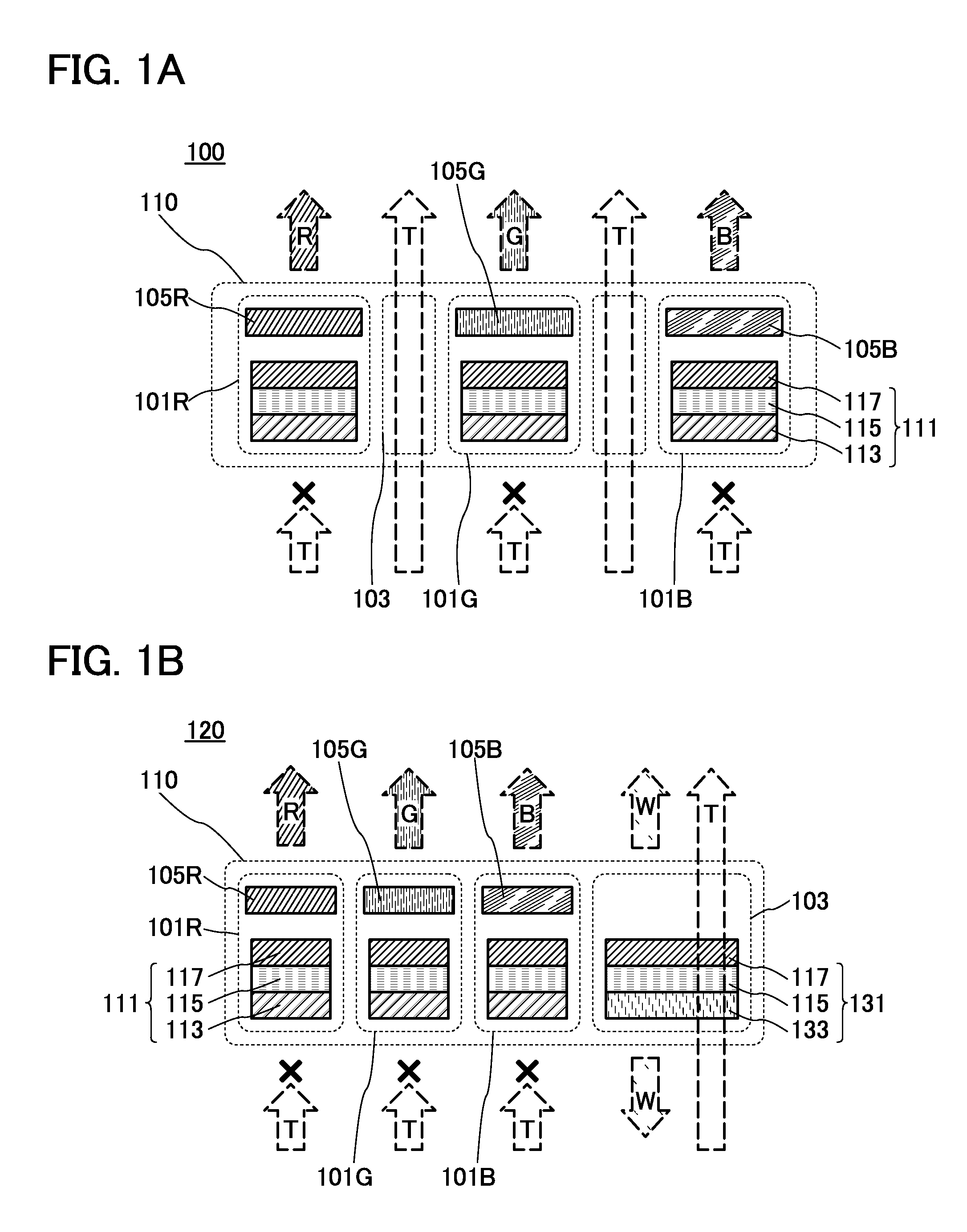
[0045]FIG. 1A is a schematic diagram of a display device 100.

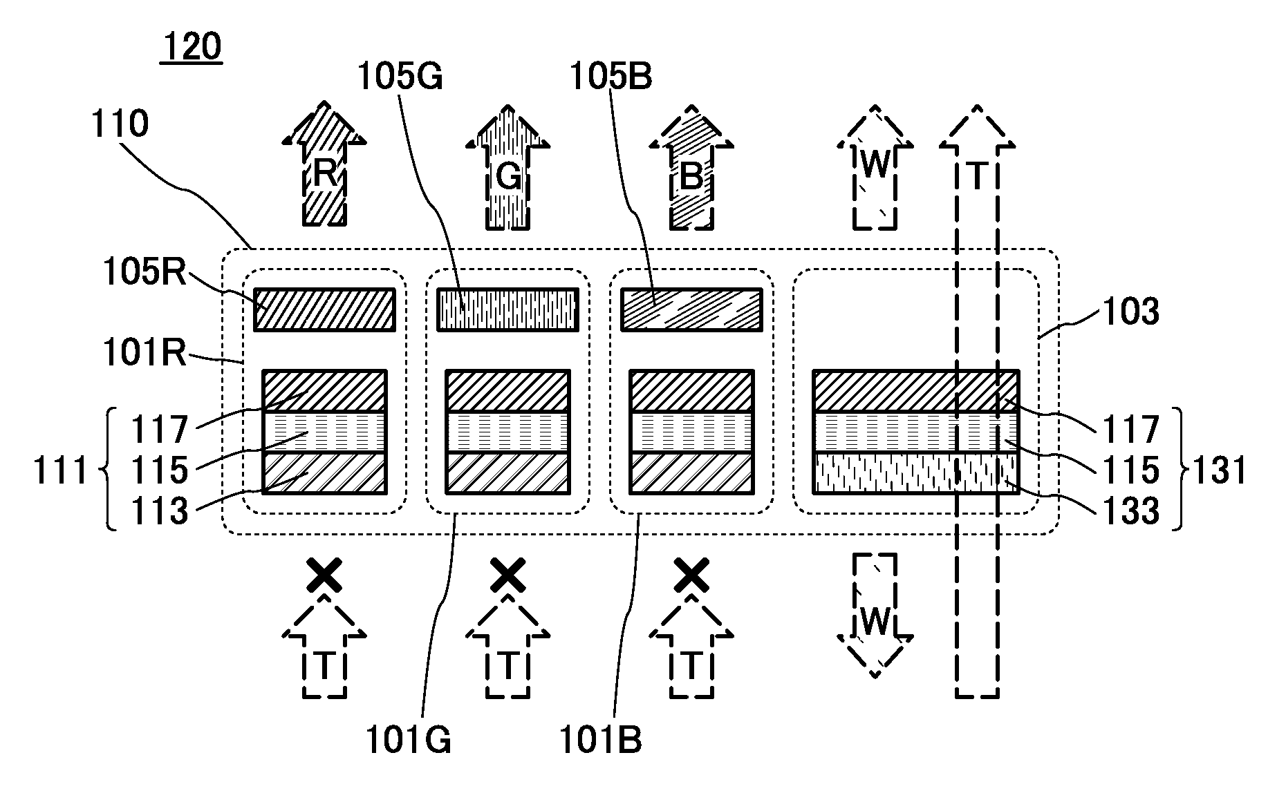
[0046]The display device 100 includes a plurality of pixels 110, and each pixel 110 includes a display element 101R emitting red light, a display element 101G emitting green light, a display element 101B emitting blue light, and a transmissive portion 103. Here, in the case where characteristics common to the display elements are described, these display elements are collectively referred to as a display element 101.

[0047]The display element 101R includes a light-emitting element 111 and a color filter 105R. Similarly, the display element 101G includes a light-emitting element 111 and a color filter 105G, and the display element 101B includes a light-emitting element 111 and a color filter 105B.

[0048]Here, in the display d...

embodiment 2

[0104]In this embodiment, a structure example of a display device including a transmissive light-emitting element in a transmissive portion will be described with reference to drawings.

[0105]The transmissive display device according to one embodiment of the present invention can employ either a simple matrix mode or an active matrix mode. An example of display device employing an active matrix mode will be described below.

[0106]FIG. 5A is a schematic top view of a display device 200 according to one embodiment of the present invention.

[0107]The display device 200 includes a first substrate 211 and a second substrate 212 which face each other. Over the first substrate 211, a display portion 201 including a plurality of pixels 110, a scan line driver circuit 202, and a signal line driver circuit 203 are provided. The first substrate 211 and the second substrate 212 are attached to each other with a sealant 213 surrounding the display portion 201, and a sealed region surrounded by the ...

structure example 3

[0127]The above structure examples shows a structure in which each of the display elements and the transmissive portion have almost the same area; however, it is preferable to increase the area of the transmissive portion by having different structures of the light-emitting element and the transmissive light-emitting element. A structure example where the area of the transmissive portion is made larger than that of each display element will be described below.

[0128]FIG. 6B is a schematic top view of a region including a pixel 110. The pixel 110 which will be described in this structure example as an example is different from that in Structure Example 1 in the area occupied by one pixel 110 and the shape of the transmissive portion 103.

[0129]Here, the pixel 110 is divided into two rows: three display elements (the display elements 101R, 101G, and 101B) are arranged in one row, and the other row is occupied by one transmissive portion 103.

[0130]The third electrode layer 133 in the tra...


PUM


Abstract

Disclosed is a display device including a pixel portion having a plurality of pixels which have a display element and a transmissive portion. The display element includes a light-emitting element which does not transmit external light, while the transmissive portion is arranged to transmit external light. In the display element, a top-emission or bottom-emission type light-emitting element is provided. On the other hand, no light-emitting element or a dual-emission type light-emitting element which possesses an EL layer interposed between two light-transmissive electrodes is provided to the transmissive portion. The emission color of the display element is controlled by a color filter which overlaps with the light-emitting element in the display element, while no color filter is given to the transmissive portion.

Description

BACKGROUND OF THE INVENTION[0001]1. Field of the Invention[0002]The present invention relates to a transmissive display device and a method for driving the transmissive display device. In particular, the present invention relates to a transmissive display device including an organic electroluminescence (EL) element and a method for driving the transmissive display device.[0003]2. Description of the Related Art[0004]An organic EL element has been actively researched and developed. In the fundamental structure of the organic EL element, a layer containing a light-emitting organic compound is provided between a pair of electrodes. By applying voltage to this element, light can be emitted from the light-emitting organic compound.[0005]A display device is one of light-emitting devices including an organic EL element. As such a display device, a display device employing a simple matrix mode (also referred to as a passive matrix mode) or an active matrix mode has been known. An organic EL ...

Claims


Application Information

Patent Timeline
IPC IPC(8): G09G5/10H05B33/06
CPCH01L27/3213H10K59/351H10K59/121G02B5/20G09G3/3208H10K59/38
Inventor YAMAZAKI, SHUNPEI
Owner SEMICON ENERGY LAB CO LTD
Why Eureka
Try Eureka