Luminous flux control member and illumination device

a technology of luminous flux and control member, which is applied in the direction of lighting and heating apparatus, semiconductor devices for light sources, instruments, etc., can solve the problem that the conventional illumination device cannot extensively illuminate a room using reflected light from ceilings or walls, and achieve high quality, prevent color irregularities, and avoid color irregularities

Active Publication Date: 2013-05-09
ENPLAS CORP
View PDF4 Cites 14 Cited by
  • Summary
  • Abstract
  • Description
  • Claims
  • Application Information

AI Technical Summary

Benefits of technology

[0015]Since the light flux controlling member according to the invention reflects a part of light from the light emitting element by the use of the transflective film and does not reflect the light from the light emitting element by total reflection, it is possible to prevent irregularity in color from occurring in emitted light and to extensively emit light from the sidewall.
[0016]The illumination device according to the invention can make the light distribution characteristics of illumination light close to the light distribution characteristics of an incandescent lamp or a fluorescent lamp. The illumination device according to the invention can emit illumination light with high quality and without irregularity in color.

Problems solved by technology

However, a conventional illumination device using an LED as a light source can emit light only in the forward direction but cannot emit light in all directions like an incandescent lamp Or a fluorescent lamp.
Accordingly, the conventional illumination device cannot extensively illuminate a room using reflected light from a ceiling or walls.

Method used


Image

  • Luminous flux control member and illumination device
  • Luminous flux control member and illumination device
  • Luminous flux control member and illumination device

Examples


embodiment 1

[0094](Embodiment 1)

[0095]Configuration of Illumination Device

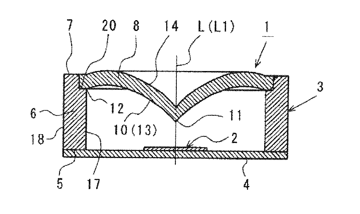
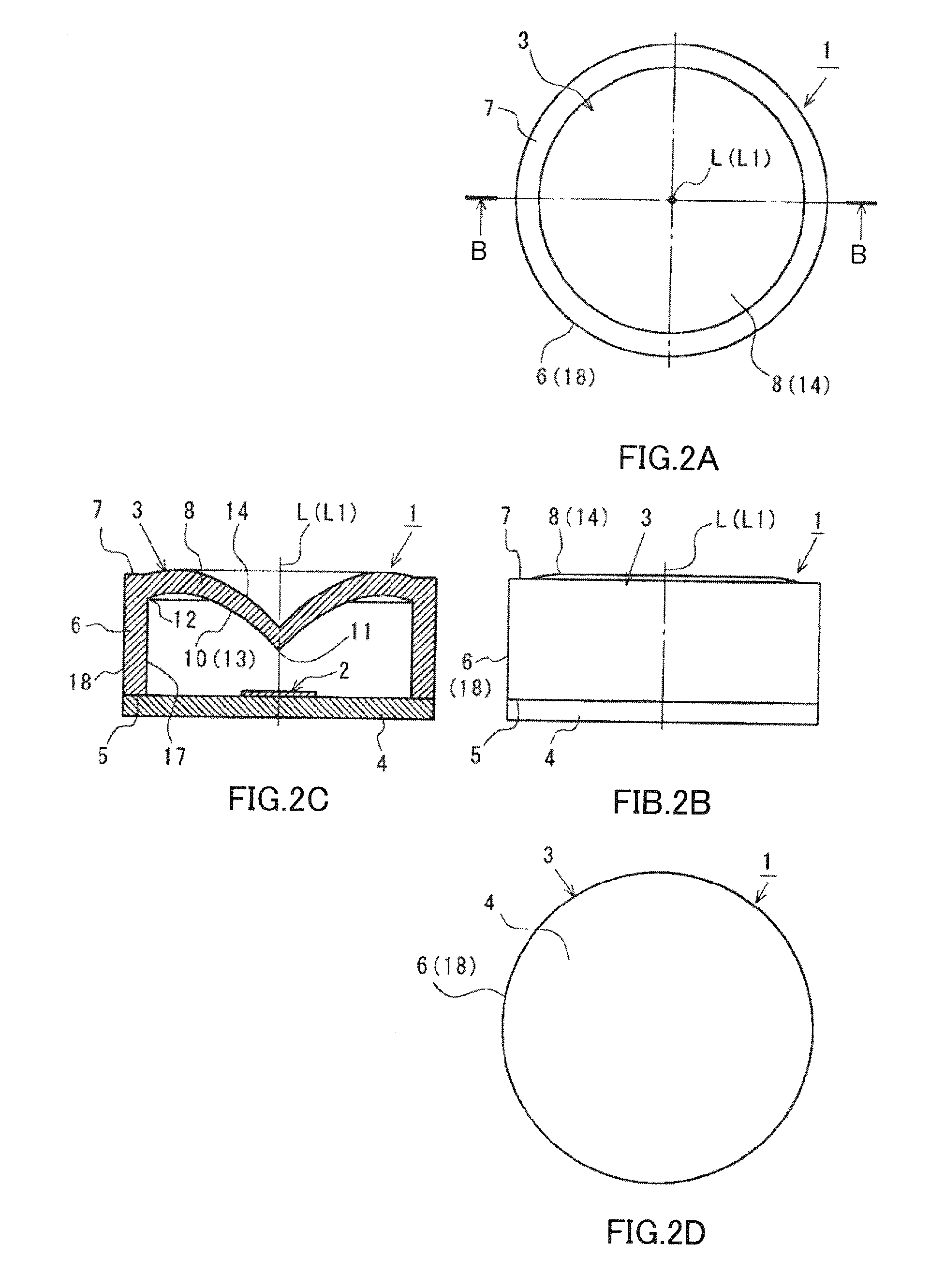
[0096]FIG. 2 is a diagram illustrating illumination device 1 according to Embodiment 1 of the invention. FIG. 2A is a plan view of illumination device 1, FIG. 2B is a front view of illumination device 1, FIG. 2C is a cross-sectional view taken along line B-B of FIG. 2A, and FIG. 2D is a bottom view of illumination device 1. Illumination device 1 can be used instead of an incandescent lamp.

[0097]As shown in FIG. 2, illumination device 1 includes light emitting element 2, light flux controlling member 3, and board 4. Illumination device 1 emits light from light emitting element 2 (for example, an LED or an LED sealed by a sealing member) through light flux controlling member 3. Light emitting element 2 and light flux controlling member 3 correspond to each other in a one-to-one manner. One end (opening end) 5 of light flux controlling member 3 is fixed to board 4 on which light emitting element 2 is mounted with an adhesive...

embodiment 2

[0121](Embodiment 2)

[0122]FIG. 10 is a cross-sectional view of illumination device 1 and light flux controlling member 3 according to Embodiment 2 (corresponding to FIG. 2C). The same elements as those of illumination device 1 and light flux controlling member 3 according to Embodiment 1 shown in FIG. 2 will not be described.

[0123]As shown in FIG. 10, light flux controlling member 3 according to Embodiment 2 is different from light flux controlling member 3 according to Embodiment 1, in that sidewall 6 and cap 8 are formed of different members, respectively. Sidewall 6 and cap 8 are formed separately. Thereafter, by inserting cap 8 into a ring-like concave portion 20 formed on the upper end of sidewall 6 and fixing them (for example, by bonding or welding), sidewall 6 and cap 8 are formed as a unified body.

[0124]When light flux controlling member 3 according to Embodiment 2 is fabricated, only cap 8 can be put into a deposition processing chamber and transflective film 13 can be for...

embodiment 3

[0126](Embodiment 3)

[0127]FIG. 12 is a cross-sectional view of illumination device 1 and light flux controlling member 3 according to Embodiment 3 (corresponding to FIG. 2C). The same elements as those of illumination device 1 and light flux controlling member 3 according to Embodiment 1 shown in FIG. 2 will not be described.

[0128]As shown in FIG. 12, light flux controlling member 3 according to Embodiment 3 is different from light flux controlling member 3 according to Embodiment 1, in that outer surface 14 of cap 8 is a plane perpendicular to optical axis L.

[0129]As shown in FIG. 13, illumination device 1 according to Embodiment 3 exhibits almost the same light distribution characteristics as the light distribution characteristics (see FIG. 7) of illumination device 1 according to Embodiment 1, except that the illuminance of the oblique front side increases, and it is thus possible to obtain the same advantages as those of illumination device 1 according to Embodiment 1. The refle...


PUM


Abstract

Disclosed is a luminous flux control member (3) comprising: a lid section (8) positioned, via an air layer, over one or two or more light-emitting elements (2) positioned on top of a substrate (4), and formed so as to intersect with the optical axis of the light-emitting elements (2); and side wall sections (6) that extend from the outer edge of the lid section (8) towards the substrate (4) side. The inner surface (10) of the lid section (8) is a concave surface with the center section thereof positioned closer to the light-emitting elements (2) than the outer peripheral section, and is covered by a transparent reflective film (13). The transparent reflective film (13) reflects some of the light from the light-emitting elements (2) towards the side wall sections (6) and allows the remaining light from the light-emitting elements (2) to pass through.

Description

TECHNICAL FIELD[0001]The present invention relates to a light flux controlling member that controls the traveling direction of light emitted from a light emitting element. The present invention relates to an illumination device having the light flux controlling member, which can be used instead of an incandescent lamp or a fluorescent lamp.BACKGROUND ART[0002]Recently, from the viewpoint of energy saving or environmental conservation, illumination devices (such as LED bulbs or LED fluorescent lamps) using a light emitting diode (LED) as a light source have been used instead of incandescent lamps or fluorescent lamps.[0003]However, a conventional illumination device using an LED as a light source can emit light only in the forward direction but cannot emit light in all directions like an incandescent lamp Or a fluorescent lamp. Accordingly, the conventional illumination device cannot extensively illuminate a room using reflected light from a ceiling or walls.[0004]In order to make li...

Claims


Application Information

Patent Timeline
Patent Type & Authority Applications(United States)
IPC IPC(8): F21V7/00
CPCF21V5/04F21V7/0016F21V13/04H01L33/58H01L33/60G02B19/0061F21Y2101/02G02B19/0066G02B19/0071G02B19/0028F21Y2105/001F21Y2105/10F21Y2115/10
Inventor NAKAMURA, MASATO
Owner ENPLAS CORP
Why Eureka
Try Eureka