Driving Engine (Water Turbine) Of Hydrokinetic Floating Power Plant With Enhanced Efficiency Degree, And Hydrokinetic Floating Power Plant Module

Inactive Publication Date: 2013-05-09
HIDRA FORCE D O O
View PDF5 Cites 19 Cited by
  • Summary
  • Abstract
  • Description
  • Claims
  • Application Information

AI Technical Summary

Benefits of technology

The present invention improves the efficiency of a hydrokinetic engine by optimizing the gaps between blades and the working channel, increasing the number of submerged blades, optimizing the blade height, and adjusting the dimensions of the confusor and diffusor. This results in a more efficient hydrokinetic floating power plant module.

Problems solved by technology

Heretofore, no effective solutions have been proposed which would increase the efficiency of energy recovery in a hydrokinetic engine.
Since the existing technical solutions have typically exhibited low efficiency, such systems have not been widely used since they lack the needed commercial cost effectiveness.
No single prior art reference mentioned above solves the technical problem of increasing efficiency, but only disclose general construction characteristics of hydroelectric power plants, and do not disclose solutions based on optimizing the efficiency of individual elements.

Method used


Image

  • Driving Engine (Water Turbine) Of Hydrokinetic Floating Power Plant With Enhanced Efficiency Degree, And Hydrokinetic Floating Power Plant Module
  • Driving Engine (Water Turbine) Of Hydrokinetic Floating Power Plant With Enhanced Efficiency Degree, And Hydrokinetic Floating Power Plant Module
  • Driving Engine (Water Turbine) Of Hydrokinetic Floating Power Plant With Enhanced Efficiency Degree, And Hydrokinetic Floating Power Plant Module

Examples


Embodiment Construction

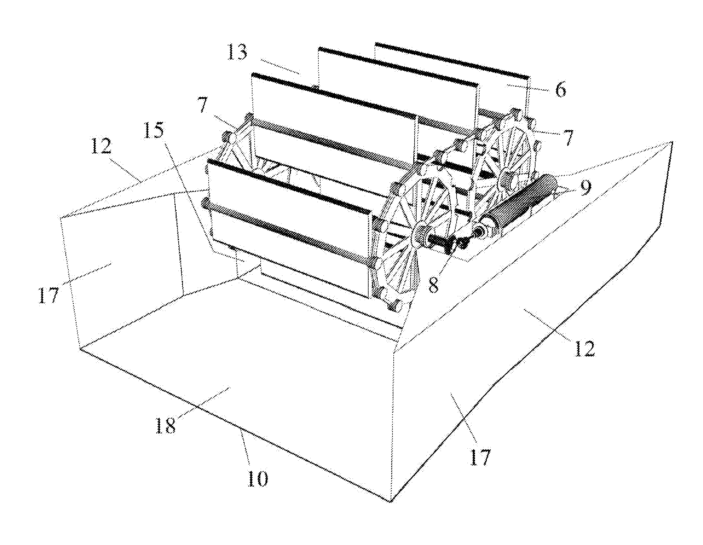
[0036]The details and parameters of the driving engine elements which contribute to an improvement of the hydrokinetic driving engine efficiency and the hydrokinetic floating power plant module efficiency were determined by implementation of commercial CDF (Computational Fluid Dynamics) software. A 2-D flow of a water stream around and within the hydrokinetic floating power plant was simulated in order to examine the influence of geometry and position of the driving engine in the water stream in system efficiency. The k-ε model of turbulence and two kinds of flow were studied, particularly:[0037]non-stationary flow with floating blades and given velocity, and[0038]stationary flow with imposed given velocity at blade equal to blade velocity.

[0039]In all cases undisturbed water incoming velocity was given and equals to 2 m / s. The following parameters were studied to analyze their impact on efficiency:[0040]1) distance t between two adjacent blades being 0.8, 3.0 and 6.0 m;[0041]2) gap...


PUM


Abstract

Improvements in hydrokinetic floating power plant efficiency are obtained by optimization of (1) gaps z and z′ between the hydrokinetic driving engine blades and internal sidewalls and floor of the working channel of the driving engine; (2) the ratio of the submerged part of blade height in liquid and part of blade height above the liquid surface; (3) the angles of inlet side planes and bottom planes of a confusor and the outlet side planes of the diffusor; and (4) distance t between blades and number n simultaneously submerged blades in the working channel of the driving engine.

Description

CROSS-REFERENCE TO RELATED APPLICATIONS[0001]The present Application is a continuation of pending International Patent Application PCT / HR2010 / 000004 filed on Feb. 22, 2010, which designates the United States, and the content of which is incorporated herein by reference.FIELD OF THE INVENTION[0002]The present invention is a hydrokinetic engine for a hydrokinetic floating power plant with enhanced efficiency, and a hydrokinetic floating power plant module for electric power generation, which uses the kinetic energy of river water flow. In particular, the invention relates to a water engine with improved individual element parameters that provide increased water flow efficiency in the water engine working channel improved power generation output of the hydrokinetic floating power plant module.[0003]The invention is referred to technical field which is according to International patent classification (IPC) designated under No. FO3B9 / 00 and refers to driving engines for liquids driven by...

Claims


Application Information

Patent Timeline
IPC IPC(8): B63H1/02
CPCF03B17/064B63H1/02Y02E10/28Y02E10/20
Inventor KORAC, IVAN
Owner HIDRA FORCE D O O
Why Eureka
Try Eureka