Impeller

a technology of turbine engines and compressors, applied in the direction of liquid fuel engines, machines/engines, efficient propulsion technologies, etc., can solve the problems of lack of aerodynamic matching between the fan and compressor stage in the off-design working point, high manufacturing costs,

Active Publication Date: 2013-05-09
RAFAEL ADVANCED DEFENSE SYSTEMS
View PDF6 Cites 14 Cited by
  • Summary
  • Abstract
  • Description
  • Claims
  • Application Information

AI Technical Summary

Benefits of technology

[0018]The present invention provides a combined fan-compressor impeller, comprising a single hub and a plurality of spaced main blades extending outwardly from said hub, an air passage channel being defined between two of said main blades, wherein each of said main blades is a mixed flow blade which continuously exten...

Problems solved by technology

Prior art turbofan engines have two stages of air compression with guide vanes between these stages, and also two shafts, resulting in high manufacturing costs due to the complex design.
Other...

Method used


Image

  • Impeller
  • Impeller
  • Impeller

Examples


Embodiment Construction

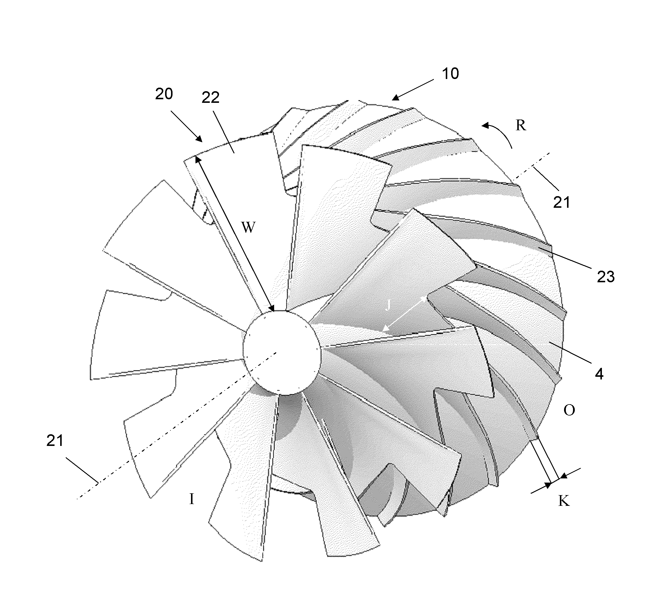
[0035]The novel impeller of the present invention comprises a single combined fan-compressor wheel positioned at the engine inlet and arranged such that each fan blade extends smoothly to a corresponding compressor blade without any axial clearance therebetween, obviating the need of stator vanes that are needed in prior art turbofan engines to guide air from the fan to the compressor. While prior art single-shaft fan-compressor sections suffer from a lack of aerodynamic matching due to the clearance between the fan and compressor, requiring guide vanes for providing such matching, at least at the design point, the unified impeller of the present invention which is configured with a plurality of mixed-flow blades provides a continuous aerodynamically smooth air path that leads to a significantly reduced diameter of the combined fan-and-compressor wheel.

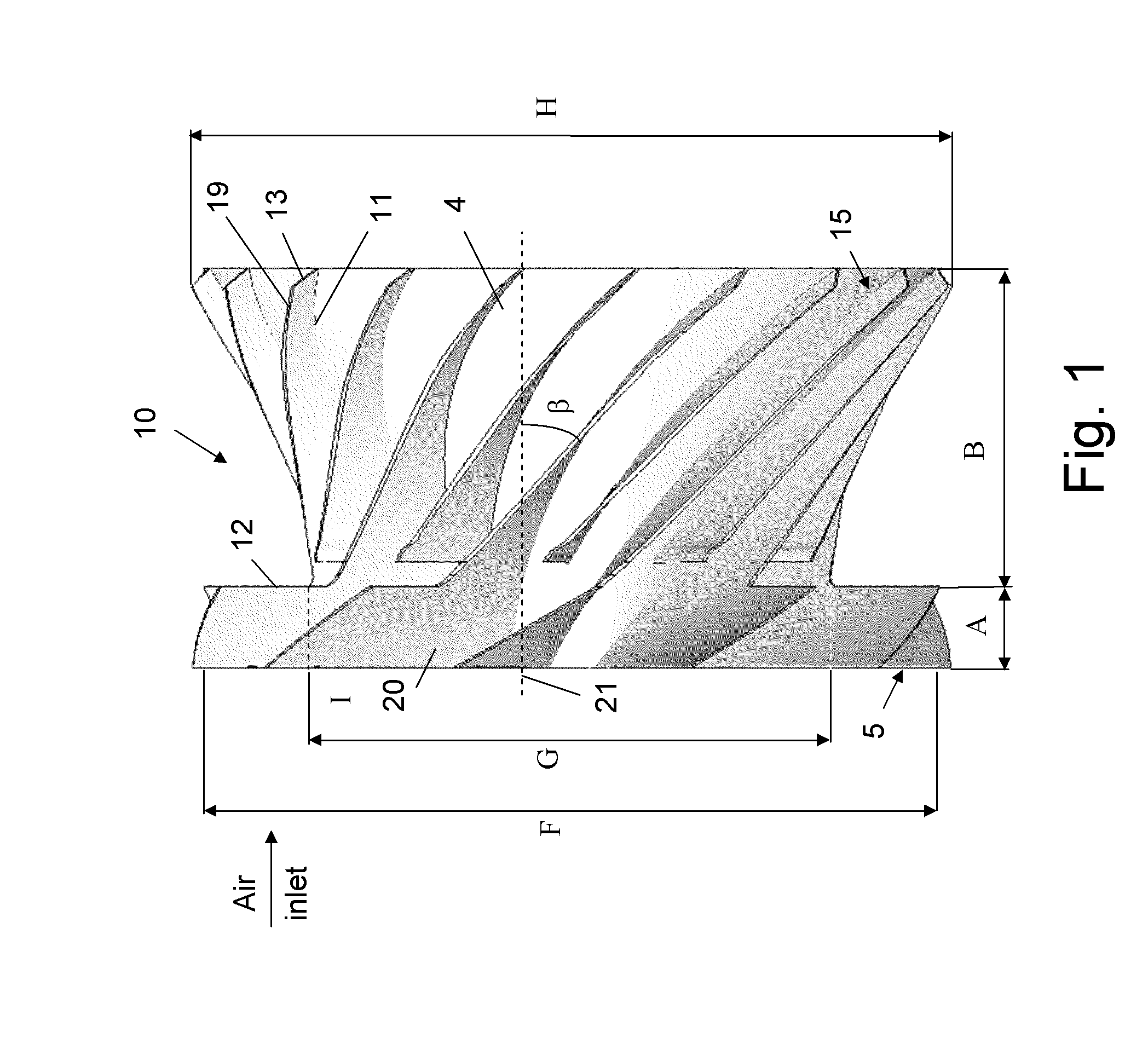
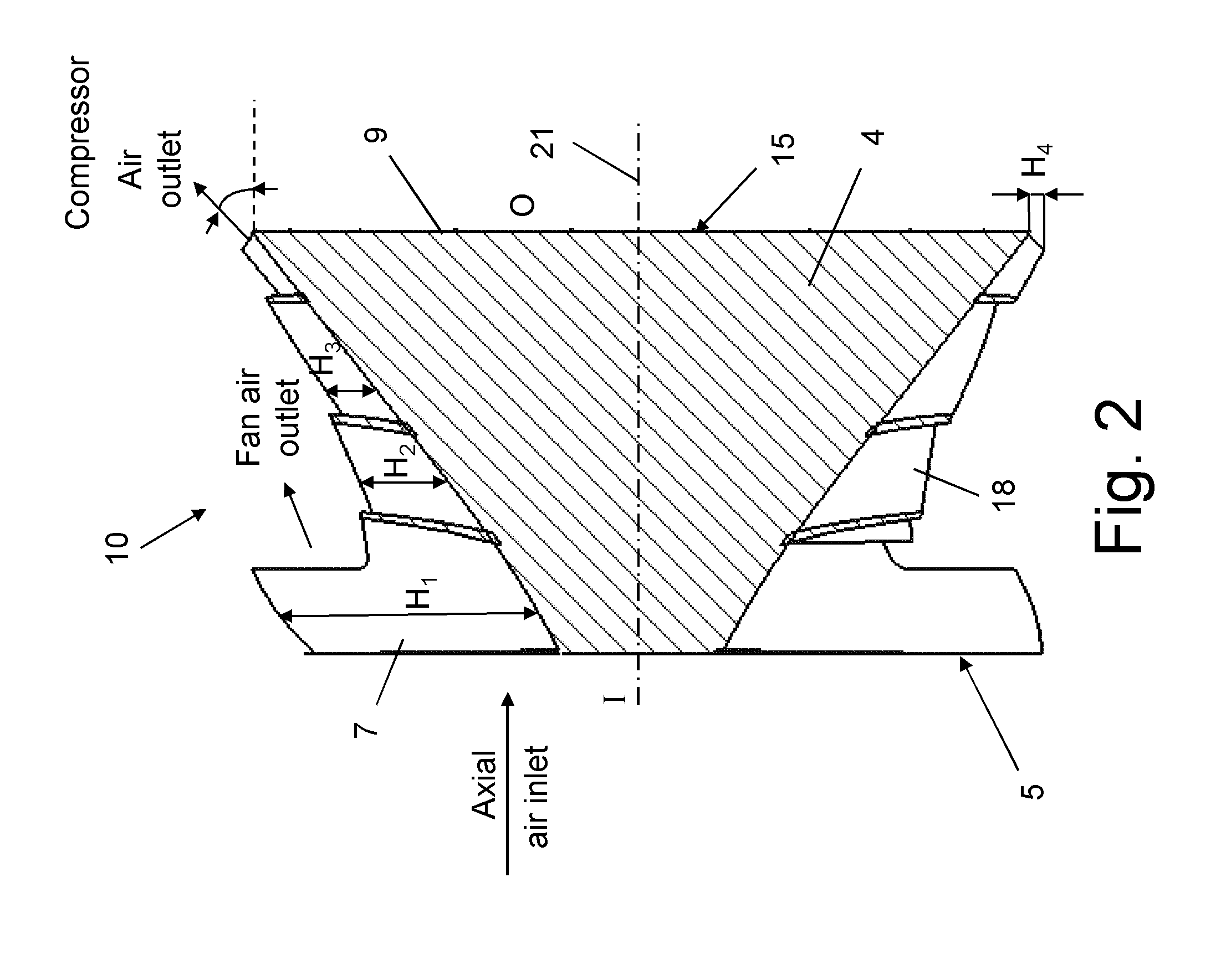
[0036]FIGS. 1-4 illustrate a novel one-wheel impeller according one embodiment of the present invention, which is generally indicate...


PUM


Abstract

A combined fan-compressor impeller comprises a single hub and a plurality of spaced main blades extending outwardly from the hub such that an air passage channel is defined between two of the main blades. Each of the main blades is a mixed flow blade which continuously extends from a fan section at an inlet end of a channel to a compressor section at an outlet end of the channel without any axial clearance between the fan section and the compressor section, providing aerodynamic matching of pressurized air flowing through the channel from the fan section to the compressor section.

Description

FIELD OF THE INVENTION[0001]The present invention relates to the field of turbofan engines and APUs. More particularly, the invention relates to a unified or combined impeller for improving performance characteristics of a turbofan engine and APUs.BACKGROUND OF THE INVENTION[0002]Small jet engines are widely used in aviation. Among other applications, small jet engines serve as main thrust units for missiles and unmanned air vehicles (UAV's), as auxiliary power units (APUs) for large airborne systems, for example to assist in starting operation of the main engines and in supplying energy for air conditioning systems.[0003]Many small jet engines suffer from poor performance resulting from a low pressure ratio due to limited rotating speed and material strength. The specific fuel consumption (SFC), which is the ratio of fuel that is consumed per time to the thrust that is generated, is conventionally reduced by bypassing a portion of the air introduced to the engine core. The engine c...

Claims


Application Information

Patent Timeline
IPC IPC(8): F04D19/00
CPCF01D5/06F01D5/142F02C3/04F02K3/06Y02T50/673F04D29/284F04D29/321F04D19/002F04D17/025F04D17/16F01D5/02F01D5/048F05D2220/50F05D2230/21F05D2230/53F05D2250/80Y02T50/60
Inventor BRONFELD, YAKOVKHOSID, SAVELY
Owner RAFAEL ADVANCED DEFENSE SYSTEMS
Why Eureka
Try Eureka