Control method and arrangement for selective catalytic reduction

a control method and catalytic reduction technology, applied in process control, separation processes, instruments, etc., can solve the problems of ammonia slippage, serious hazard of ammonia leakage, and ineffective nox reduction, and achieve the effect of simple but effectiv

Active Publication Date: 2013-05-09
WARTSILA FINLAND OY
View PDF3 Cites 8 Cited by
  • Summary
  • Abstract
  • Description
  • Claims
  • Application Information

AI Technical Summary

Benefits of technology

[0009]The NOx measurement system is activated only when it is expected that the NOx emissions have changed for some reason. This enables protection of the NOx measurement means between the measurements. The control method is also effective, since only one or two measurements and adjustments of the dosing of the reducing agent are needed after a trigger event is detected.
[0010]According to an embodiment of the present invention, the NOx concentration is measured from a by-pass duct. Clean gas can be introduced into the by-pass duct between the measurements. This is a simple but effective way of protecting the NOx measurement means.

Problems solved by technology

This applies especially to the marine applications, where leaking ammonia is a serious hazard.
If the amount of the reducing agent that is injected into the exhaust system is too small, NOx reduction is not as effective as it could be.
On the other hand, excessive dosing of the reducing agent results in ammonia slip, which means that part of the ammonia flows through the SCR system without reacting with the NOx.
Ammonia emissions are even more harmful than the NOx emissions, and therefore overdosing of the reducing agent is an undesired situation.
However, this is not an optimal solution for the reduction of ammonia slip, since NOx is formed in the oxidation process.
A problem with the control method presented above is that it is not suitable for large internal combustion engines.
In large internal combustion engines, such as in the engines used in ships and powerplants, the stabilization of the SCR system takes a relatively long time after the dosing of the reducing agent is changed, and therefore a method comprising several iteration steps is too slow.
A problem related to continuous NOx measurement is that the lifetime of a sensor that is continuously exposed to the exhaust gases is very limited.

Method used


Image

  • Control method and arrangement for selective catalytic reduction
  • Control method and arrangement for selective catalytic reduction
  • Control method and arrangement for selective catalytic reduction

Examples


Embodiment Construction

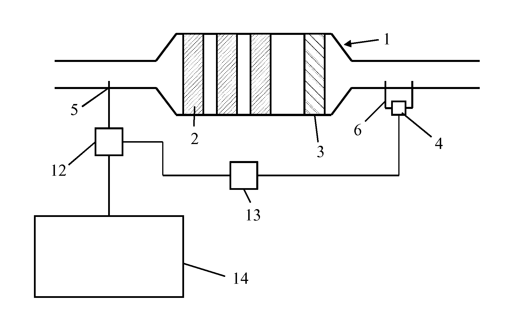
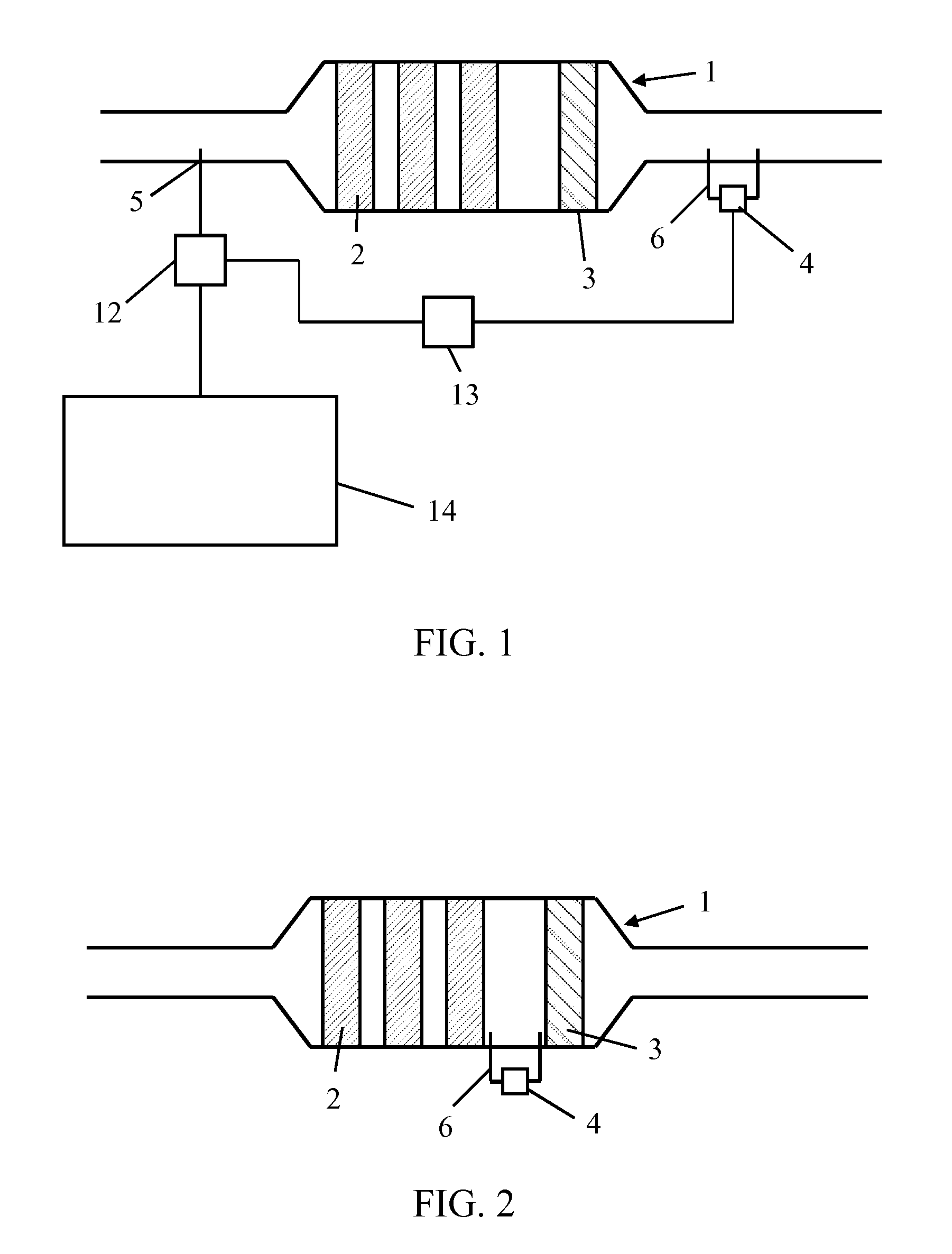
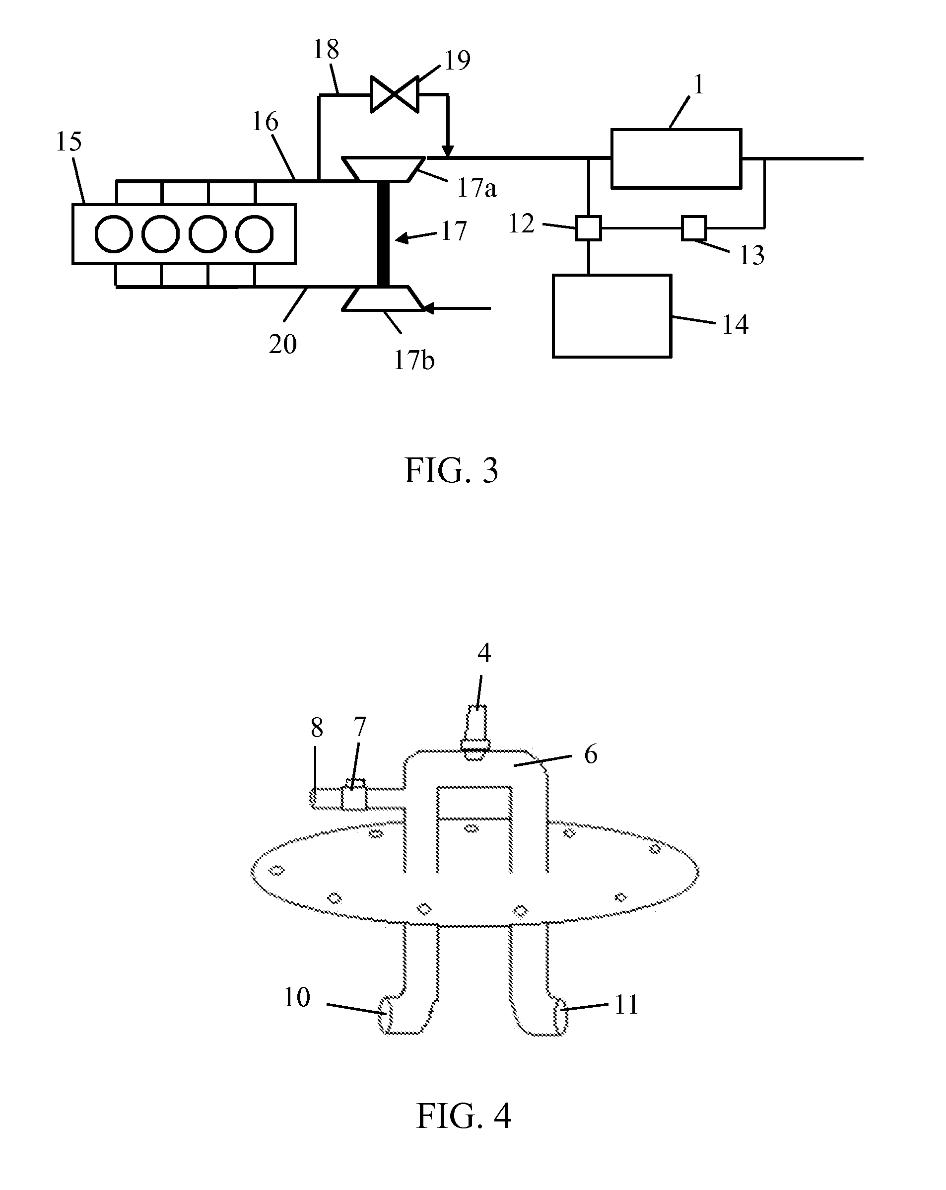
[0035]The invention is now described in more detail with reference to the accompanying drawings. In FIG. 1 is shown a simplified illustration of an SCR system for an internal combustion engine. The system comprises a catalytic converter 1 having three SCR elements 2. The SCR elements 2 are ceramic honeycomb structures that are coated with a catalyst material. Urea, which is used as the reducing agent, is injected into the exhaust gas flow upstream from the catalytic converter 1 through a reducing agent injector 5. The urea is stored in a tank 14 and dosing unit 12 ensures that the correct amount of urea solution is injected into the exhaust system. A control unit 13 is arranged to control the dosing unit 12. The urea injected into the exhaust system mixes with the exhaust gas and breaks up into ammonia and carbon dioxide due to the heat of the exhaust gas. On the surface of the SCR elements 2, ammonia molecules react with NOx and form nitrogen and water. Inside the catalytic convert...


PUM

PropertyMeasurementUnit
concentrationaaaaaaaaaa
timeaaaaaaaaaa
structureaaaaaaaaaa

Abstract

A method for controlling a selective catalytic reduction system (SCR) exploiting a set of predetermined trigger events (101) and a set point for the NOx concentration (102). At the occurrence of a trigger event (104), NOx concentration measurement downstream from the catalyst elements (2) is started (105) and the difference between the measured concentration and the set point is determined (106). If the difference is negative, the dosing of the reducing agent is decreased (107) and a new trigger event is waited for (103). If the difference is positive, the dosing of the reducing agent is increased (108). After system stabilization (109), anew measurement is started (110) and the concentration is compared to the result of the previous measurement (111). If the measured value is below the previous measured value, the same dosing is maintained (112). If the measured value is above the previous measured value, the dosing is decreased with an amount greater than the increase after the previous measurement (113). The invention also concerns an arrangement for SCR.

Description

TECHNICAL FIELD OF THE INVENTION[0001]The present invention relates to a method for controlling a selective catalytic reduction system in accordance with claim 1, and to an arrangement for selective catalytic reduction in accordance with the preamble of claim 7.BACKGROUND OF THE INVENTION[0002]Due to continuously tightening regulations concerning nitrogen oxide (NOx) emissions of internal combustion engines in ships and power plants, selective catalytic reduction (SCR) systems are becoming more and more common. With the SCR, NOx reductions of up to 90% or even greater can be achieved.[0003]In an SCR system a catalyst material and a reducing agent are used to decompose the NOx formed during the combustion back to the basic elements. The catalyst is arranged on the surface of a supporting ceramic material forming a honeycomb structure inside a reactor. On the surface of the catalyst, the NOx reacts with ammonia that is used as the reducing agent and nitrogen and water is formed. In pr...

Claims


Application Information

Patent Timeline
Patent Type & Authority Applications(United States)
IPC IPC(8): B01D53/94
CPCB01D53/9431B01D53/9495B01D2257/404B01D2258/012F01N3/106Y02T10/24F01N2410/00F01N2560/026F01N2900/08F01N2900/1402F01N3/208Y02T10/12B01D53/56B01D53/9409
Inventor NORDBERG, DANIELPELTOKOSKI, RAINE
Owner WARTSILA FINLAND OY
Why Eureka
Try Eureka