MEMS capacitive pressure sensor, operating method and manufacturing method

a capacitive pressure sensor and capacitive technology, applied in the direction of fluid pressure measurement using capacitance variation, instruments, coatings, etc., can solve the problems of insensitivity, signal drift, inaccuracy and signal drift, etc., to ensure that all mems devices are uniformly deposited or have identical geometries

Active Publication Date: 2013-05-16
SCIOSENSE BV
View PDF7 Cites 44 Cited by
  • Summary
  • Abstract
  • Description
  • Claims
  • Application Information

AI Technical Summary

Benefits of technology

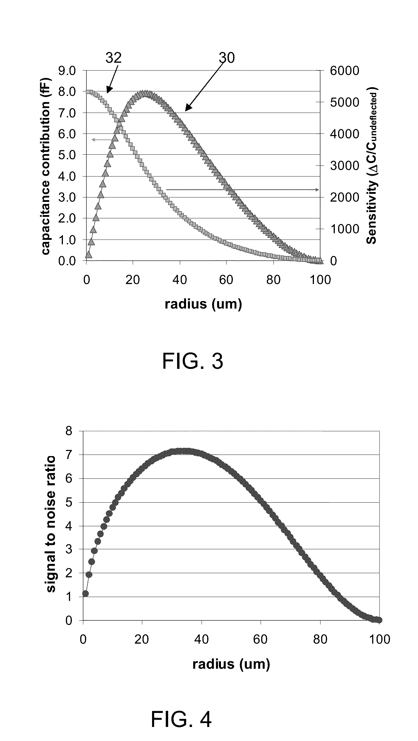
[0025]This means that the capacitance used for read out can be selected for optimum sens

Problems solved by technology

With increasing miniaturization, MEMS pressure sensors also start to suffer performance issues.
For instance, issues arise relating to insensitivity, inaccuracy and signal drift.
Although state-of-the-art deposition tools and lithographic techniques are being employed, it is impossible to ensure that all MEMS devices are uniformly deposited or have identical geometries.
Self-calibration also is needed because th

Method used


Image

  • MEMS capacitive pressure sensor, operating method and manufacturing method
  • MEMS capacitive pressure sensor, operating method and manufacturing method
  • MEMS capacitive pressure sensor, operating method and manufacturing method

Examples


Embodiment Construction

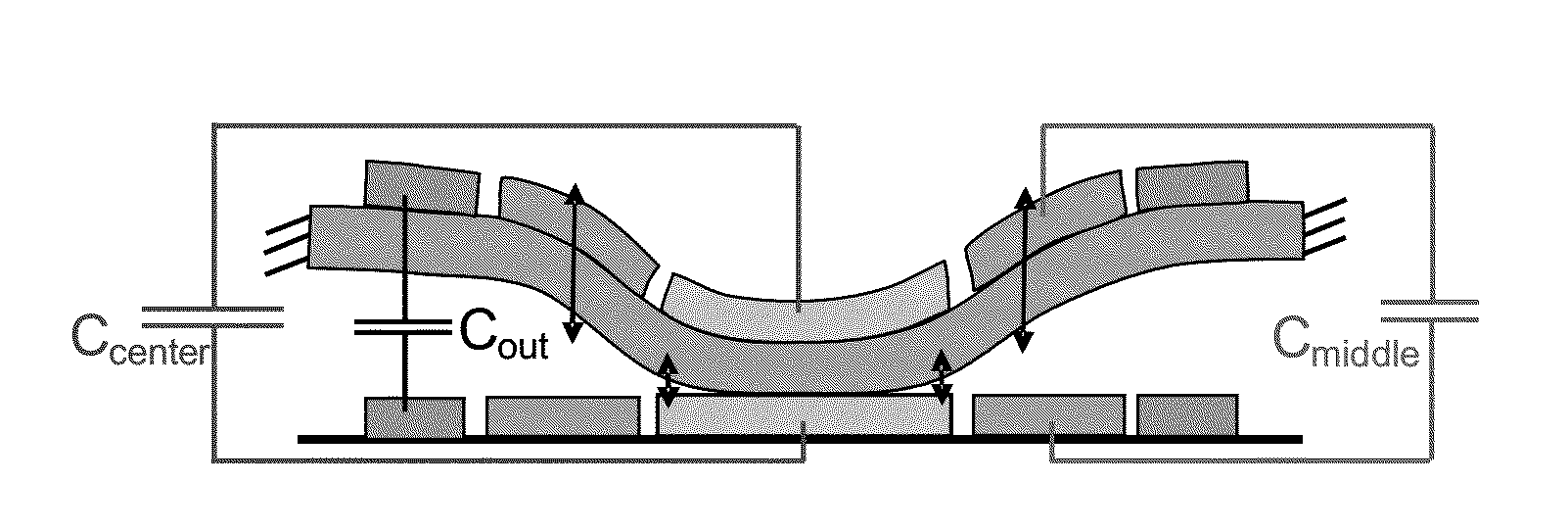
[0066]The invention provides a MEMS pressure sensor wherein at least one of the electrode arrangements comprises an inner electrode and an outer electrode arranged around the inner electrode. The capacitances associated with the inner electrode and the outer electrode are independently measured and can be differentially measured. This arrangement enables various different read out schemes to be implemented and also enables improved compensation for variations between devices or changes in device characteristics over time.

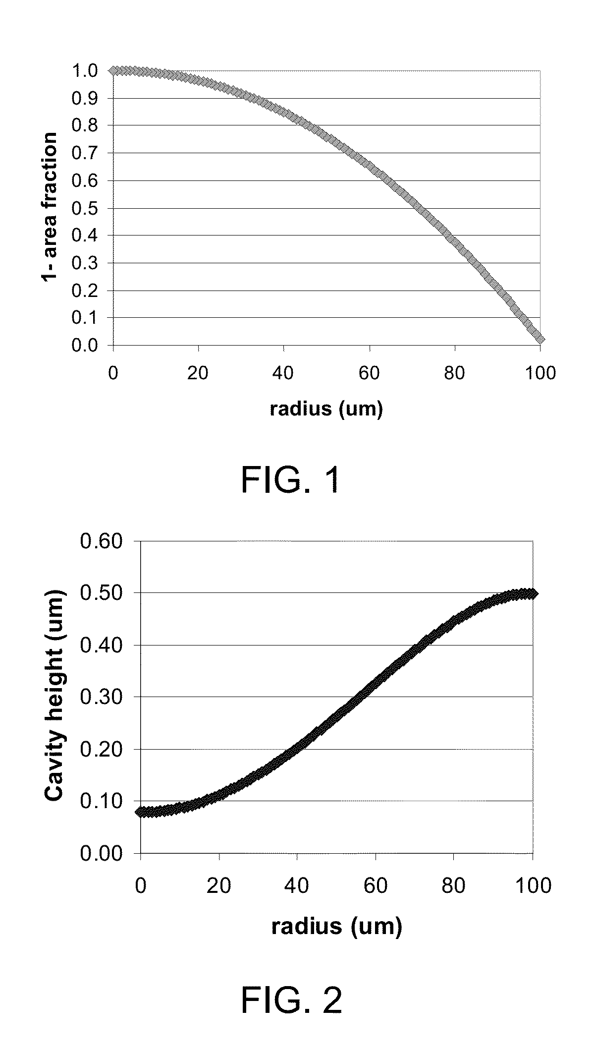
[0067]The invention makes use of different electrode areas. To understand the significance of different electrode areas at the centre and edge of the movable electrode arrangement, a geometrical analysis is useful.

[0068]FIG. 1 shows the fraction of the area of a circular surface as a function of its radius. For example, FIG. 1 shows that the surface area of a donut-like ring with an inner radius of 90 um extending to an outer radius of 100 μm covers about 20% of the...


PUM


Abstract

A MEMS pressure sensor wherein at least one of the electrode arrangements comprises an inner electrode and an outer electrode arranged around the inner electrode. The capacitances associated with the inner electrode and the outer electrode are independently measured and can be differentially measured. This arrangement enables various different read out schemes to be implemented and also enables improved compensation for variations between devices or changes in device characteristics over time.

Description

[0001]This application claims the priority under 35 U.S.C. §119 of European patent application no. 11164756.6, filed on May 4, 2011, the contents of which are incorporated by reference herein.FIELD OF THE INVENTION[0002]This invention relates to MEMS capacitive pressure sensors.BACKGROUND OF THE INVENTION[0003]MEMS pressure sensors are well known, and typically have a piezo-resistive or a capacitive read-out, to detect movement of a suspended structure when it is subjected to an external pressure. One example of known device uses a thin circular suspended SiN membrane, which is used within a capacitive MEMS pressure gauge.[0004]The cavity underneath the SiN membrane is hermitically closed by means of a PECVD SiN process, for example using a 2 μm thick PECVD SiN film. The final device performance is largely determined by the physical, mechanical and structural properties of this film and the thickness necessary to close the sacrificial etch holes. The density and composition of this ...

Claims


Application Information

Patent Timeline
IPC IPC(8): G01L9/00
CPCG01L9/0042G01L9/0073G01L9/0005G01L19/0076G01L27/002G01L9/125
Inventor BESLING, WILLEM FREDERIK ADRIANUSREIMANN, KLAUSSTEENEKEN, PETER GERARDWUNNICKE, OLAFWOLTJER, REINOUT
Owner SCIOSENSE BV
Why Eureka
Try Eureka