Substrate with carbon nanotubes, and method to transfer carbon nanotubes

a carbon nanotube and substrate technology, applied in the field of substrate, can solve the problems of low current and low mechanical stability of field emitters, and achieve the effect of long-term durability and higher currents of field electron emitters

Inactive Publication Date: 2013-05-16
SIEMENS AG
View PDF2 Cites 9 Cited by
  • Summary
  • Abstract
  • Description
  • Claims
  • Application Information

AI Technical Summary

Benefits of technology

[0007]An object of the present invention is to achieve CNTs on a substrate that enable higher currents and long-term durability of field electron emitters for use in computer tomography.

Problems solved by technology

Disadvantages of the conventional techniques for manufacturing substrates with carbon nanotubes are the low currents and the low mechanical stability of the field emitters.

Method used


Image

  • Substrate with carbon nanotubes, and method to transfer carbon nanotubes
  • Substrate with carbon nanotubes, and method to transfer carbon nanotubes
  • Substrate with carbon nanotubes, and method to transfer carbon nanotubes

Examples


Embodiment Construction

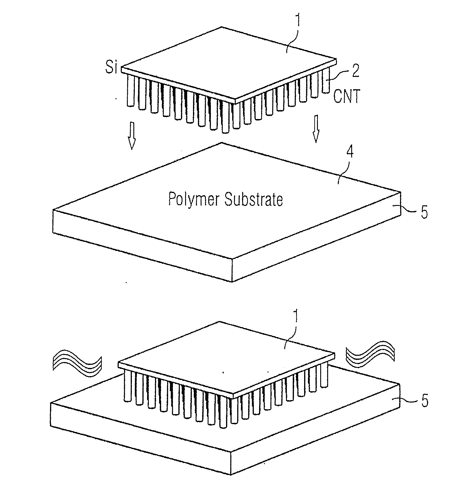
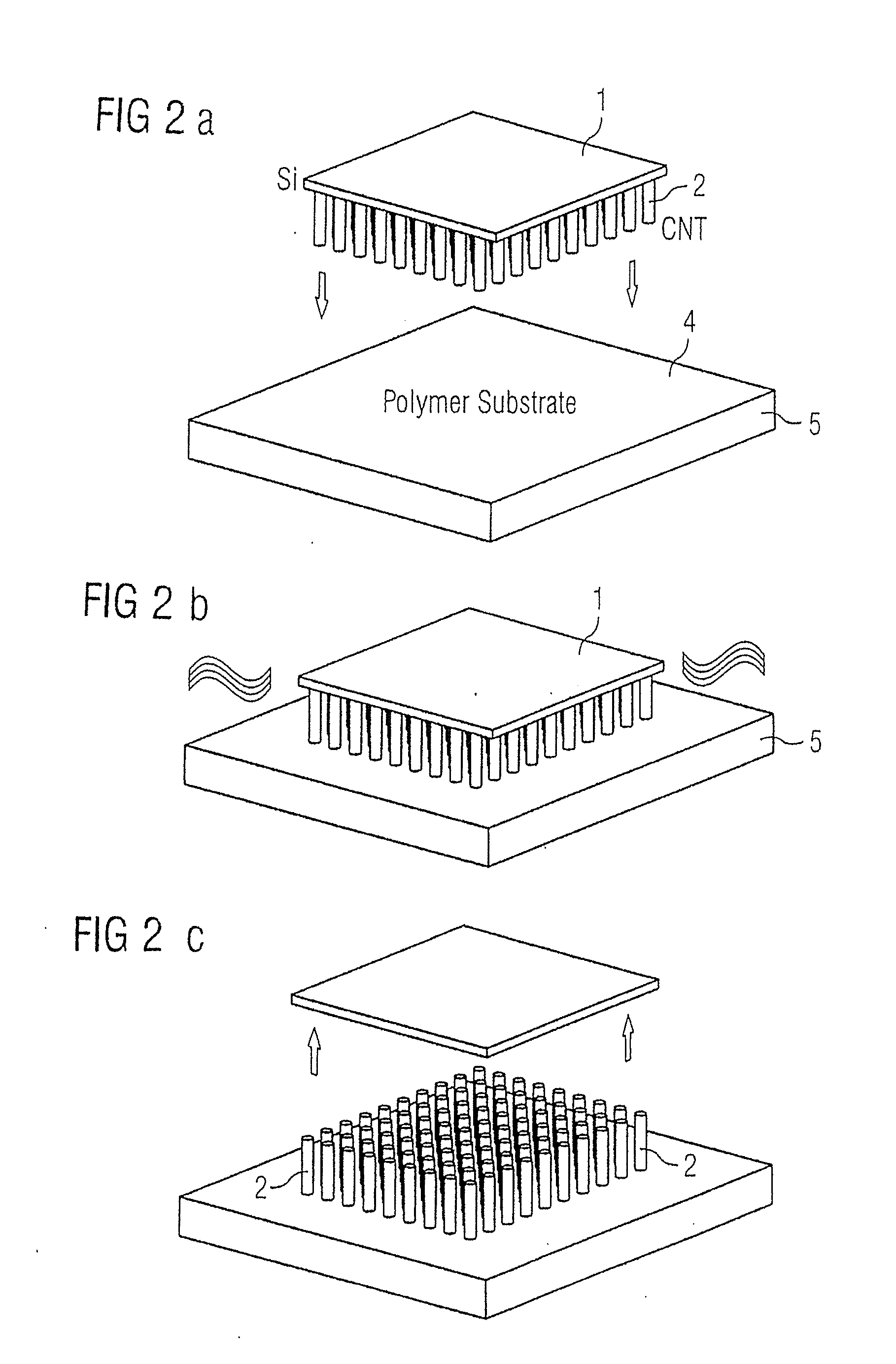
[0017]For example, the aligned CNTs are produced as follows:

a)

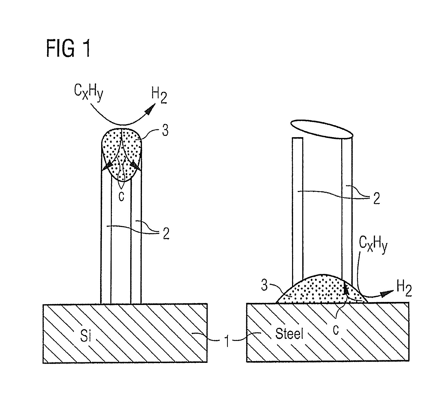
[0018]The oven is heated to a deposition temperature of approximately 775° C. To grow the aligned CNTs, a saturated ferrocene solution is injected into xylol. Due to the iron in the ferrocene as a catalyst particle, the CNTs can grow on the metallic surface, either in a tip growth mode (thus with the incorporation of the catalytic iron particle) or in a base growth mode (thus while leaving the catalytic iron particle behind on the substrate surface). In which mode the CNTs ultimately grow depends on the interaction of the substrate surface with the catalyst particle.

[0019]The CNT growth is determined by the interaction between the catalyst particle and the substrate. Weak bonds between the catalyst and the substrate lead to tip growth mode, strong bonds lead to the base growth mode.

[0020]The preferred length of the CNTs is thereby between 2 to 10 and 50 μm.

[0021]All types of metals can be used as electrically conductive s...


PUM

PropertyMeasurementUnit
tube diameteraaaaaaaaaa
temperatureaaaaaaaaaa
lengthaaaaaaaaaa

Abstract

A substrate for field emitters uses carbon nanotubes (CNTs) on a conductive substrate, the CNTs being erected essentially perpendicular to the substrate and aligned. In a method to transfer a CNT forest from a first substrate to a second substrate, the second substrate is coated with adhesive and the peaks (tips) of the CNTs on the first substrate are embedded in the uncurred adhesive on the second substrate. After the adhesive cures, the CNTs are removed from the first substrate with the peaks anchored in the cured adhesive on the second substrate.

Description

RELATED APPLICATION[0001]The present application is a divisional of Ser. No. 13 / 075,401, filed Mar. 30, 2011.BACKGROUND OF THE INVENTION[0002]1. Field of the Invention[0003]The invention concerns a substrate with carbon nanotubes, (CNTs) and methods to transfer carbon nanotubes from one substrate to another.[0004]2. Description of the Prior Art[0005]Electron field emitters can be constructed with the use of carbon nanotubes. Arranged in a vacuum vessel with anode, novel x-ray tubes can be realized in this manner.[0006]Disadvantages of the conventional techniques for manufacturing substrates with carbon nanotubes are the low currents and the low mechanical stability of the field emitters.SUMMARY OF THE INVENTION[0007]An object of the present invention is to achieve CNTs on a substrate that enable higher currents and long-term durability of field electron emitters for use in computer tomography.[0008]It is general knowledge that CNTs are ideal field emitters because they are as conduc...

Claims


Application Information

Patent Timeline
Patent Type & Authority Applications(United States)
IPC IPC(8): H01J9/02
CPCH01J1/304H01J9/025Y10T428/24058H01J2235/06H01J2201/30469
Inventor ZEININGER, HEINRICH
Owner SIEMENS AG
Why Eureka
Try Eureka