Rotating Control System and Method for Providing a Differential Pressure

a control system and differential pressure technology, applied in the direction of survey, insulation, borehole/well accessories, etc., can solve the problems of more tool joints, wear of the interior sealing surface of the sealing element, and inability to provide differential pressure, etc., to achieve the effect of safe operation and higher safety factor

Active Publication Date: 2013-05-16
WEATHERFORD TECH HLDG LLC
View PDF1 Cites 13 Cited by
  • Summary
  • Abstract
  • Description
  • Claims
  • Application Information

AI Technical Summary

Benefits of technology

The patent describes a method and system for using a high pressure rated RCD in drilling wellbores. The method involves limiting the fluid pressure differential to which the RCD sealing element is exposed, and adjusting the cavity fluid pressure and temperature in the RCD cavity to reduce the pressure difference. The cavity fluid can be water, drilling fluid, gas, lubricant, coolant, or hydraulic fluid. The method can be used in a drill-to-the-limit drilling method, where surface backpressure is applied, allowing for the use of lighter mud weight and the identification of weak components in the pressure containment system. The higher pressure rated RCD allows for drilling of deeper wellbores with larger end tubulars opening area, such as casings or production liners, than other methods.

Problems solved by technology

The continuous movement of the tubular through the sealing element while the sealing element is under pressure causes wear of the interior sealing surface of the sealing element.
The sealing element is inherently limited in the number of times it can be fatigued with tool joints that pass under high differential pressure conditions.
Of course, the deeper the wellbores are drilled, the more tool joints that will be stripped through sealing elements, some under high pressure.
However, unlike the RCD tubular sealing elements discussed above, the seals that are lubricated in the '107 patent do not seal with the tubular.

Method used


Image

  • Rotating Control System and Method for Providing a Differential Pressure
  • Rotating Control System and Method for Providing a Differential Pressure
  • Rotating Control System and Method for Providing a Differential Pressure

Examples


Embodiment Construction

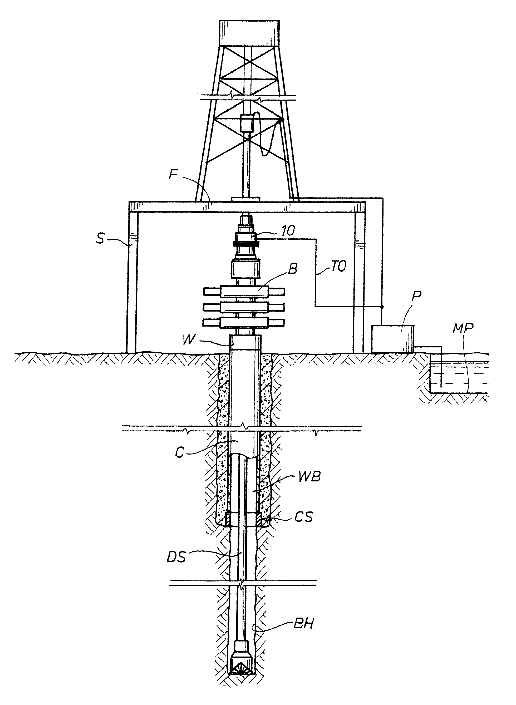
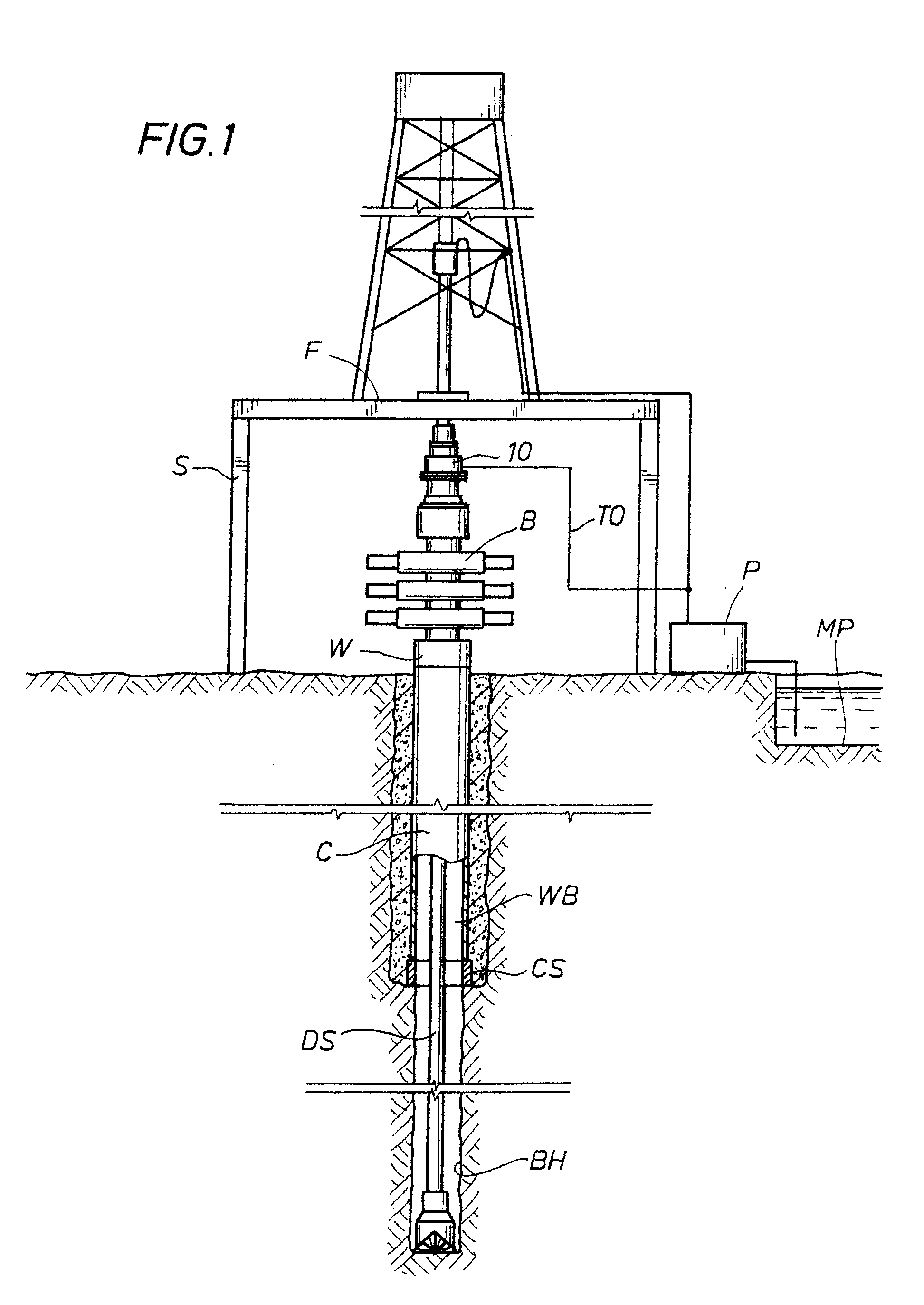
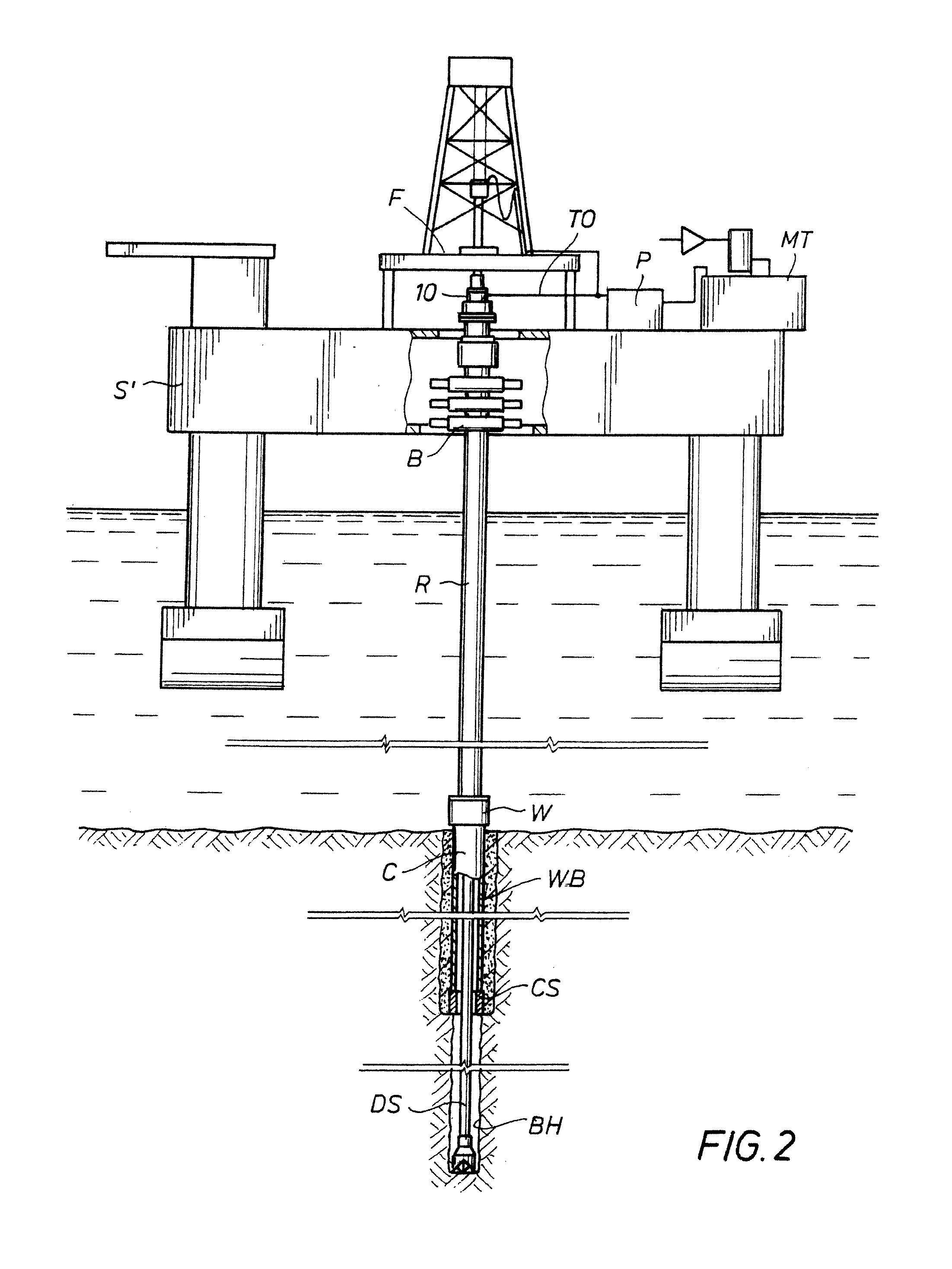
[0046]The DTTL method and the pressure sharing RCD systems may be used in many different drilling environments, including those environments shown in FIGS. 1 and 2. Exemplary drilling rigs or structures for use with the invention, generally indicated as S, are shown in FIGS. 1 and 2. Although a land drilling rig S is shown in FIG. 1, and an offshore floating semi-submersible rig S is shown in FIG. 2, other drilling rig configurations and embodiments are contemplated for use with the invention for both offshore and land drilling. For example, the invention is equally applicable to drilling rigs such as jack-up, semi-submersibles, submersibles, drill ships, barge rigs, platform rigs, and land rigs. Turning to FIG. 1, an RCD 10 is positioned below the drilling deck or floor F of the drilling rig S and above the BOP stack B. RCD 10 may include any of the RCD pressure sharing systems shown in FIGS. 7 to 17B or other adequately pressure rated RCD. The RCD, where possible, should be sized ...


PUM


Abstract

A Drill-To-The-Limit (DTTL) drilling method variant to Managed Pressure Drilling (MPD) applies constant surface backpressure, whether the mud is circulating (choke valve open) or not (choke valve closed). Because of the constant application of surface backpressure, the DTTL method can use lighter mud weight that still has the cutting carrying ability to keep the borehole clean. The DTTL method identifies the weakest component of the pressure containment system, such as the fracture pressure of the formation or the casing shoe leak off test (LOT). With a higher pressure rated RCD, such as 5,000 psi (34,474 kPa) dynamic or working pressure and 10,000 psi (68,948 kPa) static pressure, the limitation will generally be the fracture pressure of the formation or the LOT. In the DTTL method, since surface backpressure is constantly applied, the pore pressure limitation of the conventional drilling window can be disregarded in developing the fluid and drilling programs. Using the DTTL method a deeper wellbore can be drilled with larger resulting end tubulars, such as casings and production liners, than had been capable with conventional MPD applications.

Description

CROSS-REFERENCE TO RELATED APPLICATIONS[0001]This application is a divisional of co-pending application Ser. No. 12 / 462,266 filed Jul. 31, 2009 (U.S. Pat. No. 8,347,983, issue date Jan. 8, 2013), which is hereby incorporated by reference in its entirety for all purposes.STATEMENT REGARDING FEDERALLY SPONSORED RESEARCH OR DEVELOPMENT[0002]N / AREFERENCE TO MICROFICHE APPENDIX[0003]N / ABACKGROUND OF THE INVENTION[0004]1. Field of the Invention[0005]The present invention relates to rotating control devices used when drilling wells and methods for use of these rotating control devices.[0006]2. Description of the Related Art[0007]Rotating control devices (RCDs) have been used for many years in the drilling industry for drilling wells. An internal sealing element fixed with an internal member of the RCD seals around the outside diameter of a tubular and rotates with the tubular. The tubular may be slidingly run through the RCD as the tubular rotates or when the tubular, such as a drill strin...

Claims


Application Information

Patent Timeline
Patent Type & Authority Applications(United States)
IPC IPC(8): E21B33/13
CPCE21B21/00E21B33/085E21B36/001E21B33/13E21B43/10E21B21/08E21B47/06E21B47/07E21B21/085E21B19/00E21B21/10E21B33/03
Inventor HANNEGAN, DON M.BAILEY, THOMAS F.JACOBS, MELVIN T.WHITE, NICKY A.HOYER, CAREL W.
Owner WEATHERFORD TECH HLDG LLC
Why Eureka
Try Eureka