Centrifugal De-Clutch

a centrifugal and clutch technology, applied in mechanical actuated clutches, vertical landing/taking-off aircraft, braking systems, etc., can solve problems such as motors generating unwanted hea

Active Publication Date: 2013-05-16
WISK AERO LLC
View PDF9 Cites 69 Cited by
  • Summary
  • Abstract
  • Description
  • Claims
  • Application Information

AI Technical Summary

Benefits of technology

[0007]In one embodiment, a rotor assembly of an aircraft comprises a rotor, a motor comprising a stationary part and a rotating part, and the centrifugal de-clutch. In particular, the centrifugal de-clutch is coupled to the rotating part of the motor such that the flexures of the de-clutch preload the high friction pads against the stationary part of the motor. The high friction pads prevent the rotor from rotating until the motor generates enough torque to overcome the friction force generated by the friction pads. As the rotational speed of the rotor increases, a proof mass that is mounted to or that is a part of each flexure applies a centrifugal force on the friction pads that counteracts the flexure preload. Above a certain speed threshold, the friction pads are completely disengaged from the stationary part of the motor, thereby allowing the rotor to rotate freely.

Problems solved by technology

Supplying the energy required to keep the rotor stationary drains energy from a battery that provides the energy to the motor and also causes the motor to generate unwanted heat.

Method used


Image

  • Centrifugal De-Clutch
  • Centrifugal De-Clutch
  • Centrifugal De-Clutch

Examples


Embodiment Construction

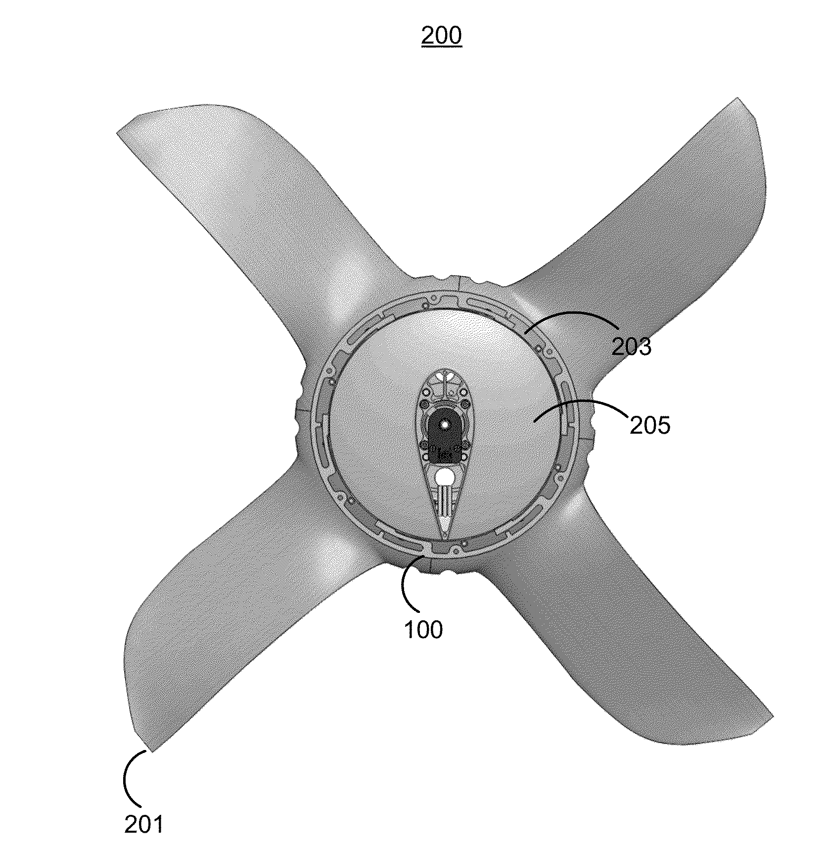
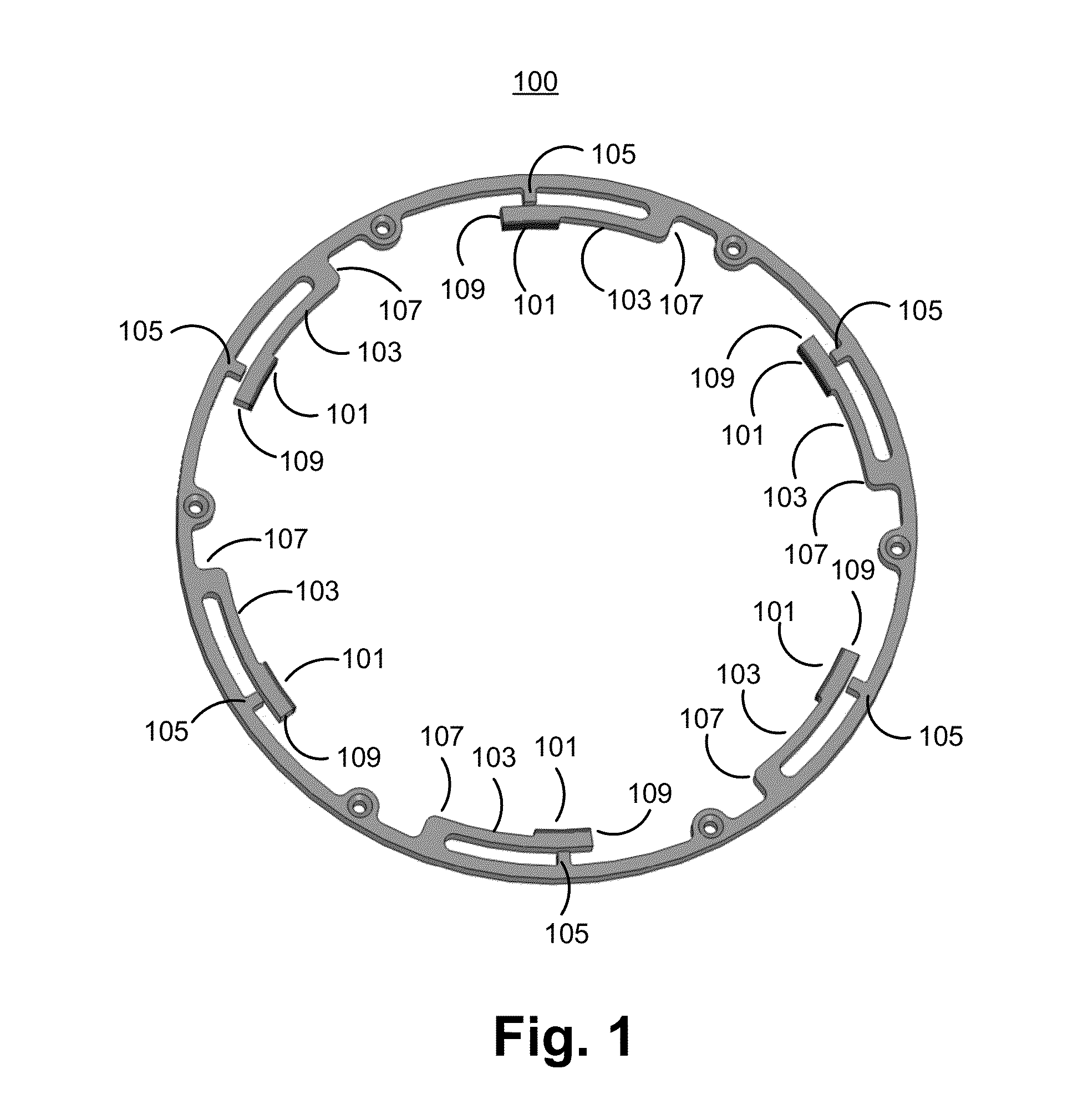
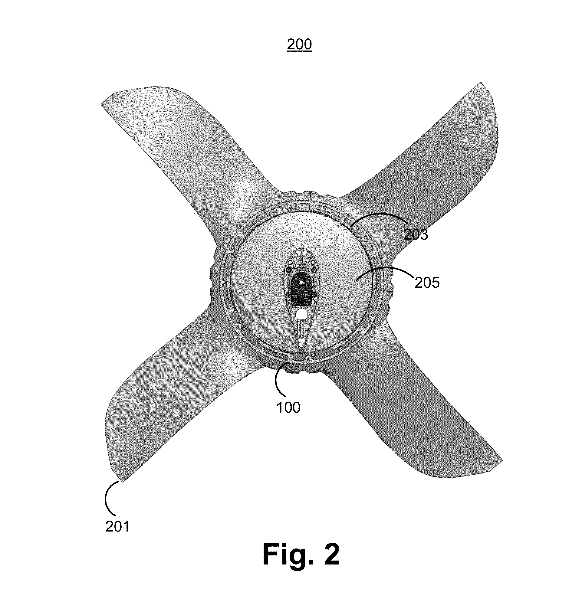
[0014]FIG. 1 illustrates a centrifugal de-clutch 100 in accordance with one embodiment. The centrifugal de-clutch 100 is a mechanical mechanism that mechanically prevents a rotor of an aircraft from rotating. In one embodiment, the centrifugal de-clutch is constructed out of metal (e.g., steel, titanium, or aluminum) or composite material (e.g., carbon fiber or Kevlar). Note that in other embodiments other materials may be used to construct the centrifugal de-clutch.

[0015]In one embodiment, the centrifugal de-clutch is a circular ring comprising a plurality of friction pads 101, a plurality of flexures 103, and a plurality of stop tabs 105. The friction pads 101 are composed of brake pad material (asbestos, organic, or semi-metallic formulations) that provide a high coefficient of friction such as 0.1 to 5. Note that other coefficients of friction may be used. The flexures 103 are curved arms each comprising a first end 107 and a second end 109 according to one embodiment. In one em...


PUM


Abstract

A mechanical mechanism is used to prevent a rotor of an aircraft from rotating when the rotor is not in use. The mechanical mechanism disengages when the speed of the rotor exceeds a speed threshold and the mechanism reengages when the speed of the rotor is below the speed threshold.

Description

BACKGROUND[0001]1. Field of the Invention[0002]This disclosure describes mechanical mechanisms that mechanically prevent a rotor from rotating below a threshold speed, but allow the rotor to rotate freely above the threshold speed.[0003]2. Description of Related Art[0004]The rotary wing aircraft, or helicopter, is one common type of vertical takeoff and landing (VTOL) aircraft. VTOL aircraft have large rotors that provide either or both both vertical and horizontal thrust. Often, when a rotor is not being used, the rotor is kept stationary.[0005]Conventional systems typically use a motor that is coupled to the rotor and adapted to prevent the rotor from rotating when it is not in use. The motor applies a torque to keep the rotor stationary. Thus, conventional systems require the supply of energy to the motor in order to reject disturbance torques that would cause the rotor to rotate. Supplying the energy required to keep the rotor stationary drains energy from a battery that provide...

Claims


Application Information

Patent Timeline
Patent Type & Authority Applications(United States)
IPC IPC(8): F16D43/18
CPCF16D43/18F16D2043/145B64C11/04B64C27/48Y10T477/86F16D59/02Y10T477/816Y10T477/847B64C29/0025
Inventor LONG, GEOFFREY A.
Owner WISK AERO LLC
Why Eureka
Try Eureka