
Image heating device

a heating device and image technology, applied in the field of image heating devices, can solve the problems of inability to meet the needs of recording materials, etc., to achieve substantial deterioration in productivity, reduce temperature difference, and reduce the effect of temperature differen

Inactive Publication Date: 2013-05-16
CANON KK
View PDF9 Cites 11 Cited by
  • Summary
  • Abstract
  • Description
  • Claims
  • Application Information

AI Technical Summary

Benefits of technology

The present invention is about an image heating device that can keep the temperature difference between the non-sheet passing part and the sheet passing part low, even if the target temperature for heating the image is reduced. This helps to increase productivity when conveying recording material with a narrow width.

Problems solved by technology

Consequently, since the movement velocity of the image heating member is different between the non-sheet passing portion and the sheet passing portion of the image heating member, when a recording material with a wide width is subsequently conveyed to the nip portion, the conveyance of the recording material may become unstable.
However, the heat generation efficiency of the image heating member tends to deteriorate when the temperature of the image heating member is around the Curie temperature.
However, the following issues may occur if the above-described image heating member is used in an image heating device in which the target temperature of the image heating member is set to a low temperature when a recording material having a small heat capacity, such as thin paper, is conveyed to the nip portion.
More specifically, the temperature difference between the sheet passing portion and the non-sheet passing portion is too great.
Consequently, the stability of subsequent recording materials' conveyance properties may become unstable.
However, this results in a deterioration in productivity.

Method used


Image

  • Image heating device
  • Image heating device
  • Image heating device

Examples


Embodiment Construction

[0025]Various exemplary embodiments, features, and aspects of the invention will be described in detail below with reference to the drawings.

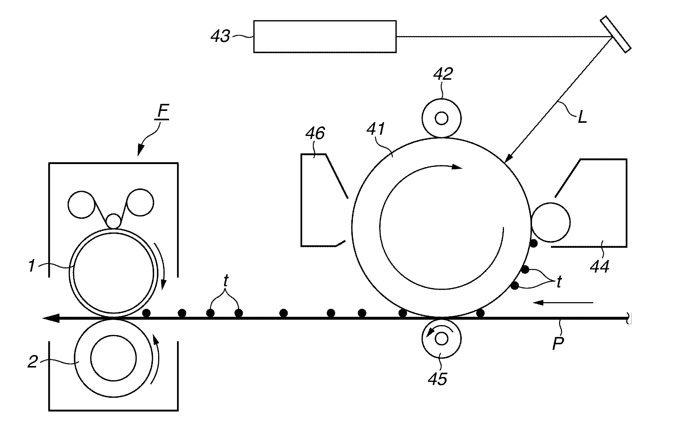
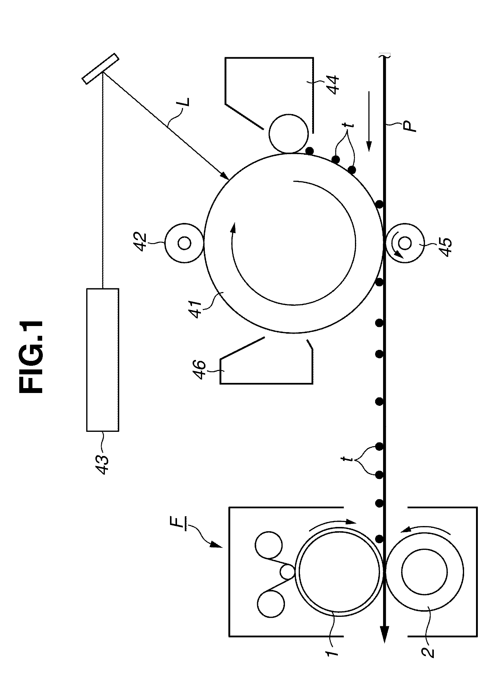
[0026]FIG. 1 is a schematic configuration model diagram illustrating an example of an image forming apparatus that includes an electromagnetic induction heating type image heating and fixing device according to a first exemplary embodiment of the present invention.

[0027]First, an image forming unit for forming a toner image on a recording material will be described. A rotating drum type photosensitive member (a photosensitive drum) 41 serving as an image bearing member is rotatably driven at a predetermined circumferential speed in the direction of the arrow. The photosensitive drum 41 is uniformly charged to a predetermined negative dark potential Vd by a primary charging device 42 during the course of rotation. A laser beam scanner 43 scans and exposes a uniformly charged face of the photosensitive drum 41 by outputting a laser beam L that is...


PUM


Abstract

An electromagnetic induction heating type image heating device is capable of preventing image defects caused by an increase in the temperature of a non-sheet passing portion during thin paper passage, and uses a magnetic shunt alloy having a predetermined Curie temperature. The image heating device is configured to heat a material based on heat generated by an eddy current generated in a conductive member by inducing a magnetic field in a conductive member with a magnetic flux generation unit. The conductive member includes a magnetic shunt alloy whose composition is adjusted to have a predetermined Curie temperature. The image heating device includes a cooling device configured to cool an end portion of the conductive member. Consequently, the image heating device can increase a cooling effect by the cooling device during thin paper passage, in which a fixing temperature is lower than during plain paper passage.

Description

BACKGROUND OF THE INVENTION[0001]1. Field of the Invention[0002]The present invention relates to an image heating device capable of heating a toner image on a recording material. This image heating device is used in an image forming apparatus, such as a copying machine, a printer, and a facsimile. More particularly, the present invention relates to an electromagnetic induction heating type image heating device.[0003]2. Description of the Related Art[0004]Conventionally, electrophotographic image forming apparatuses have included an image heating device that heats and fixes on a recording material a toner image formed on the recording material. Generally, this image heating device includes an image heating member for heating the toner on the recording material, and a nip forming member that presses against the image heating member to form a nip portion through which the recording material is sandwiched and conveyed. The image heating device heats the toner image at the nip portion. J...

Claims


Application Information

Patent Timeline
Patent Type & Authority Applications(United States)
IPC IPC(8): H05B6/06
CPCH05B6/06H05B6/105H05B6/145G03G15/2053G03G15/2017G03G15/2042H05B2206/023
Inventor YAMAMOTO, NAOYUKI
Owner CANON KK
Learn More