Power Conversion Device and Temperature Rise Calculation Method Thereof

a technology of conversion device and temperature rise, which is applied in the direction of electric generator control, dynamo-electric converter control, dynamo-electric gear control, etc., can solve the problems of complex mounting structure and device complexity

Inactive Publication Date: 2013-05-16
HITACHI LTD
View PDF2 Cites 24 Cited by
  • Summary
  • Abstract
  • Description
  • Claims
  • Application Information

AI Technical Summary

Benefits of technology

[0015]According to the preferred embodiment of the present invention, a temperature rise caused in a power conversion device can be calculated with a simple method in which a current command value and

Problems solved by technology

This may result in a complex mounting structure.
A mechanism is also required that reads an instantaneous current by using a signal tha

Method used


Image

  • Power Conversion Device and Temperature Rise Calculation Method Thereof
  • Power Conversion Device and Temperature Rise Calculation Method Thereof
  • Power Conversion Device and Temperature Rise Calculation Method Thereof

Examples


embodiment 1

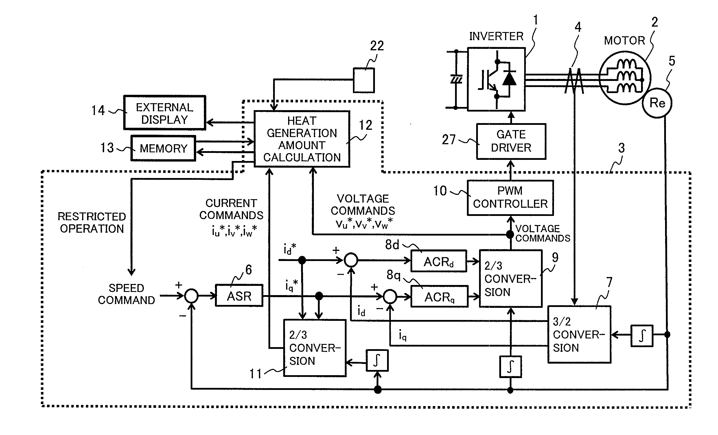
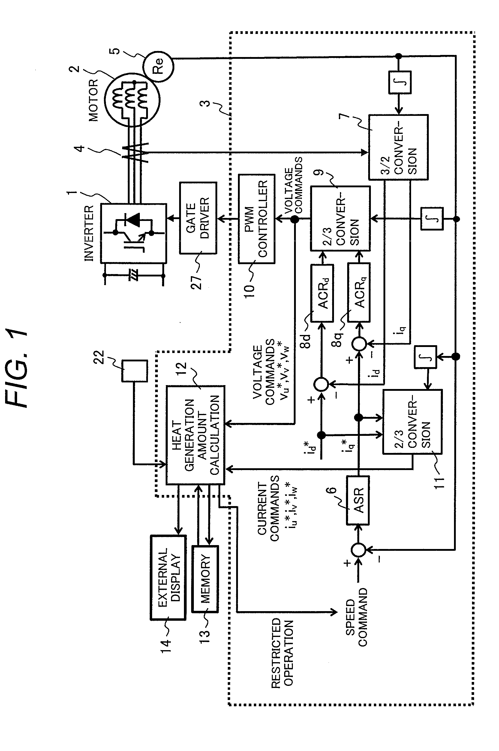
[0034]FIG. 1 schematically shows the entire structure of a power conversion device in a first embodiment of the present invention.

[0035]As a main circuit, the power conversion device includes an inverter main circuit 1 and a motor 2 that is powered and driven by the inverter main circuit 1.

[0036]As a controller, the power conversion device includes a control circuit 3 that performs calculations to control the inverter main circuit 1 and calculates the amount of heat generated in the inverter main circuit 1, a current detector 4 that is used as a sensor to detect a current output from the inverter main circuit 1 to the motor 2, and a rotary encoder 5 that detects the magnetic pole position of the motor 2 and its rotational speed.

[0037]In this embodiment, the control circuit 3 has a heat generation amount calculation unit 12 that calculates the amount of heat generated at the chip of a switching element in the inverter main circuit 1 from a command value used in calculation in a contr...

embodiment 2

[0097]FIG. 17 schematically shows the entire structure of a power conversion device in a second embodiment of the present invention. The second embodiment relates to a method in which a current flowing in the motor 2 is estimated from a current flowing in a DC part without using the current sensor 4 in the first embodiment.

[0098]In this embodiment, the current flowing in the DC part is measured from a voltage generated across, for example, a shunt resistor 25, and field current id component and torque current iq component are derived by a current calculation unit 26 in the control and calculation unit 3. In the second embodiment as well, the command values id* and iq* for these currents are calculated. Accordingly, as in the first embodiment, the current command values iu*, iv* and iw* for currents flowing in the elements in all phases can be calculated by the current command 2-phase / 3-phase converting unit 11. The voltage command value vu*, vv* or vw* can also be similarly calculat...


PUM


Abstract

A temperature rise of a semiconductor switching element, which is part of a power conversion device such as an inverter, is estimated by an extremely simple method to assess the degradation and remaining lifetime of the semiconductor switching element.
In a heat generation amount calculation unit 12 in a calculation processor 3, current command values Id* and Iq* and voltage command values vu*, vv* and vw* are used to calculate a chip loss. First, current values iu*, iv* and iw* of all output phases are estimated from the current command values. The ON/OFF loss of the chip is represented by a function of an estimated value for a current flowing in each output phase, and the loss can be derived by integration with a PWM carrier frequency f. In addition, with respect to a conduction loss, it is necessary to integrate a conduction time with the estimated current value and a saturation voltage, which is a function of the estimated current value. In this case, the conduction time is calculated from a relationship between a carrier amplitude and the voltage command value in each control cycle fsw of the switching element. In addition, an ambient temperature sensor is added to calculate an absolute temperature.

Description

FIELD OF THE INVENTION[0001]The present invention relates to a power conversion device and the method of calculating a temperature rise caused by the power conversion device, and more particularly to a power conversion device that assesses the degradation and remaining lifetime of a semiconductor switching element used in the power conversion device and the method of calculating a temperature rise caused by the power conversion device.BACKGROUND OF THE INVENTION[0002]With the method of estimating the lifetime of a semiconductor device and a semiconductor power converter described in patent document (PD) 1, a temperature detector is connected to the base plate of an IGBT element of an inverter and the number of ripple temperatures is counted in each temperature range.[0003]With the elevator controller described in patent document (PD) 2, a lifetime assessment method is not addressed, but a loss per chip is calculated from, for example, an output signal from a current detector to prev...

Claims


Application Information

Patent Timeline
IPC IPC(8): H02P29/00H02M7/48H02P21/00H02P21/14H02P21/18H02P21/22H02P21/24H02P23/14H02P23/16H02P27/06H02P27/08
CPCH02M1/32H02M2001/327H02P21/06H02M7/5387H02P29/0088H02P29/68H02M1/327
Inventor AYANO, HIDEKIISHIKAWA, KATSUMIOGAWA, KAZUTOSHIKOMINAMI, TSUTOMUKUNIHIRO, MAMI
Owner HITACHI LTD
Why Eureka
Try Eureka