Supercharge Your Innovation With Domain-Expert AI Agents!

Common multi-purpose actuator to control antenna remote electrical tilt, remote azimuth steering and remote azimuth beam-width control

a multi-purpose actuator and antenna technology, applied in the field of communication systems and components, can solve problems such as flexible hardware designs

Active Publication Date: 2013-05-16
INTEL CORP
View PDF8 Cites 25 Cited by
  • Summary
  • Abstract
  • Description
  • Claims
  • Application Information

AI Technical Summary

Benefits of technology

The present invention provides a remote controlled actuator system for adjusting the radiation emission pattern of an antenna. The system includes an antenna with movable portions and two or more actuators, each actuator controlling a different portion of the antenna. The actuators are controlled by a master controller that sends control signals to the actuators and receives feedback signals from the actuators. The feedback signals include rotational position feedback and motor position feedback. The system also includes a mechanical coupling assembly with a bracket mount plate and actuator mount plates that secure the actuators to the antenna and position them in response to rotation of the actuators. The actuator mount plates have holes receiving the shaft pin and pivotally coupling the shaft pin, securing the actuators to the antenna and positioning them in meshing engagement with the actuator control circuit. The system also includes a data bus connecting the actuator control circuits and a bracket mount plate with curved toothed racks and first and second plates that pivot in opposite directions in response to rotation of the actuators. The system allows for adjustment of the radiation emission pattern of the antenna without the need for physical contact between the actuators and the antenna.

Problems solved by technology

Systems employing RET, RAS, and RAB can already be met by existing designs, but designers struggle with hardware designs that can be flexible enough to meet industry requirements such as the AISG (“Antenna Interface Standards Group”) v1 and AISGv2 tower mounted specifications, while meeting competitive cost targets.

Method used


Image

  • Common multi-purpose actuator to control antenna remote electrical tilt, remote azimuth steering and remote azimuth beam-width control
  • Common multi-purpose actuator to control antenna remote electrical tilt, remote azimuth steering and remote azimuth beam-width control
  • Common multi-purpose actuator to control antenna remote electrical tilt, remote azimuth steering and remote azimuth beam-width control

Examples


Embodiment Construction

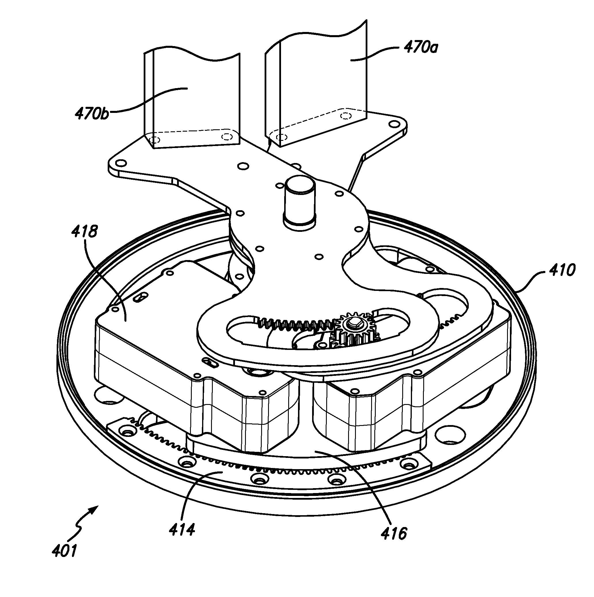
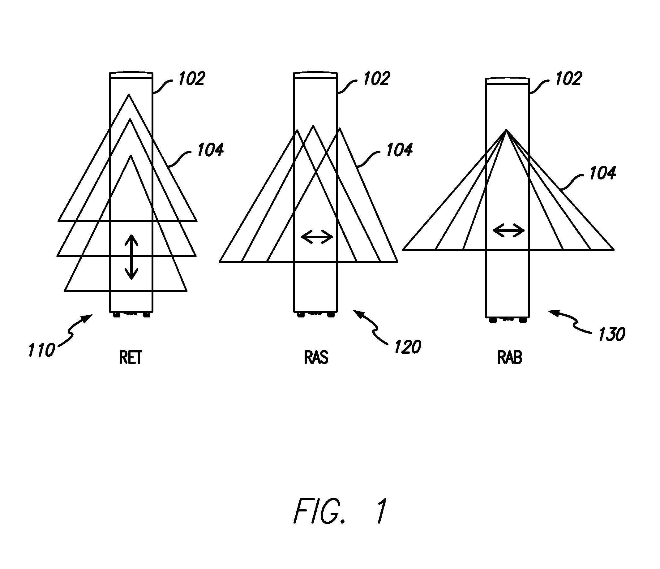
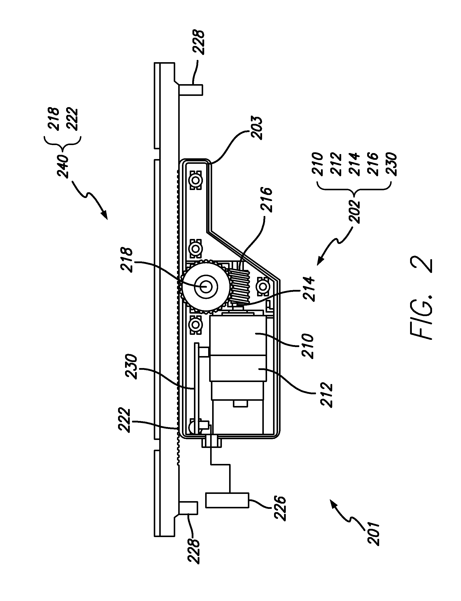
[0034]A single common actuator for systems employing RET, RAS and RAB is disclosed. RET, RAS, and RAB control utilizing the disclosed actuator may employ the teachings of U.S. Pat. No. 7,505,010 entitled “ANTENNA CONTROL SYSTEM” and U.S. Pat. No. 7,990,329 entitled “DUAL STAGGERED VERTICALLY POLARIZED VARIABLE AZIMUTH BEAM-WIDTH ANTENNA FOR WIRELESS NETWORK,” the disclosures of which are incorporated herein by reference in their entirety. Remote electrical tilt is varied when the actuator slides the phase shifter dielectrics as disclosed in U.S. Pat. No. 7,505,010 for example. Remote azimuth steering is varied when the actuator rotates the antenna center around its base as disclosed in U.S. Pat. No. 7,990,329 for example. Remote azimuth beam-width is varied when the actuator opens and closes the scissor assembly as disclosed in U.S. Pat. No. 7,990,329 for example. It shall be understood, however, that the examples illustrated in the disclosures of these patents as well as exemplary ...


PUM


Abstract

A common multi-purpose actuator to control antenna remote electrical tilt, remote azimuth steering, and remote azimuth beam-width control is disclosed. A single stepper motor uses a Hall-sensor for closed loop positioning feedback. Serial and parallel communications are employed through the same harness to the motor control circuit. The driven shaft of the motor turns a self-locking worm-gear which rotates a mating shaft which drives the necessary gearing. The actuator assembly can be arranged in multiple or single output configurations. DC line filtering improves the antenna signal to spurious noise ratio.

Description

RELATED APPLICATION INFORMATION[0001]The present application claims priority under 35 U.S.C. Section 119(e) to U.S. Provisional Patent Application Ser. No. 61 / 559,496 filed Nov. 14, 2011, the disclosure of which is incorporated herein by reference in its entirety.BACKGROUND OF THE INVENTION[0002]1. Field of the Invention[0003]The present invention relates in general to communication systems and components. More particularly, the present invention is directed to antennas for wireless networks.[0004]2. Description of the Prior Art and Related Background Information[0005]Base station antennas require low power consumption and high interoperability compatibility. Antennas must pass and transmit signals with minimum distortion and loss. Until recently, antennas have been passive devices, with their radiation pattern steering controlled by means of static mechanical mounts. With advances in computer networking, dynamic remote electro-mechanical control of antennas is possible. Antenna sys...

Claims


Application Information

Patent Timeline
IPC IPC(8): H01Q3/04
CPCH01Q1/246H01Q3/04
Inventor LEVER, SEANHUNT, NANDOYANG, CHING-SHUNSIDERIS, GEORGEFIORELLO, CARMINE M.RABINOVICH, ALEXANDER
Owner INTEL CORP
Features
  • R&D
  • Intellectual Property
  • Life Sciences
  • Materials
  • Tech Scout
  • Unparalleled Data Quality
  • Higher Quality Content
  • 60% Fewer Hallucinations
Learn More