Eureka AIR delivers breakthrough ideas for toughest innovation challenges, trusted by R&D personnel around the world.

Spatial light modulating panel using transmittive liquid crystal display panel and 3D display device using the same

a technology of transmitting liquid crystal display panel and spatial light modulating panel, which is applied in the direction of fibre light guide, application, instruments, etc., can solve the problems of large volume and huge weight, insufficient application of conventional arts for holography type 3d display system to thin, light and portable display system, system is thicker and expensive than, and achieves easy and simple structure. , the effect of low manufacturing cos

Active Publication Date: 2013-05-16
LG DISPLAY CO LTD
View PDF8 Cites 12 Cited by
  • Summary
  • Abstract
  • Description
  • Claims
  • Application Information

AI Technical Summary

Benefits of technology

The present invention provides a spatial light modulator and a 3D display using the same that can produce holography 3D images / videos using just one transitive liquid crystal panel. This is achieved by conducting phase modulation of the back light at two neighboring pixels, respectively, and combining the two modulated lights to produce holography 3D images in the space between the SLM and the observer. The controlling method and system configuration for holography 3D images / videos are simple, and the display system is easy to manufacture and has low manufacturing costs.

Problems solved by technology

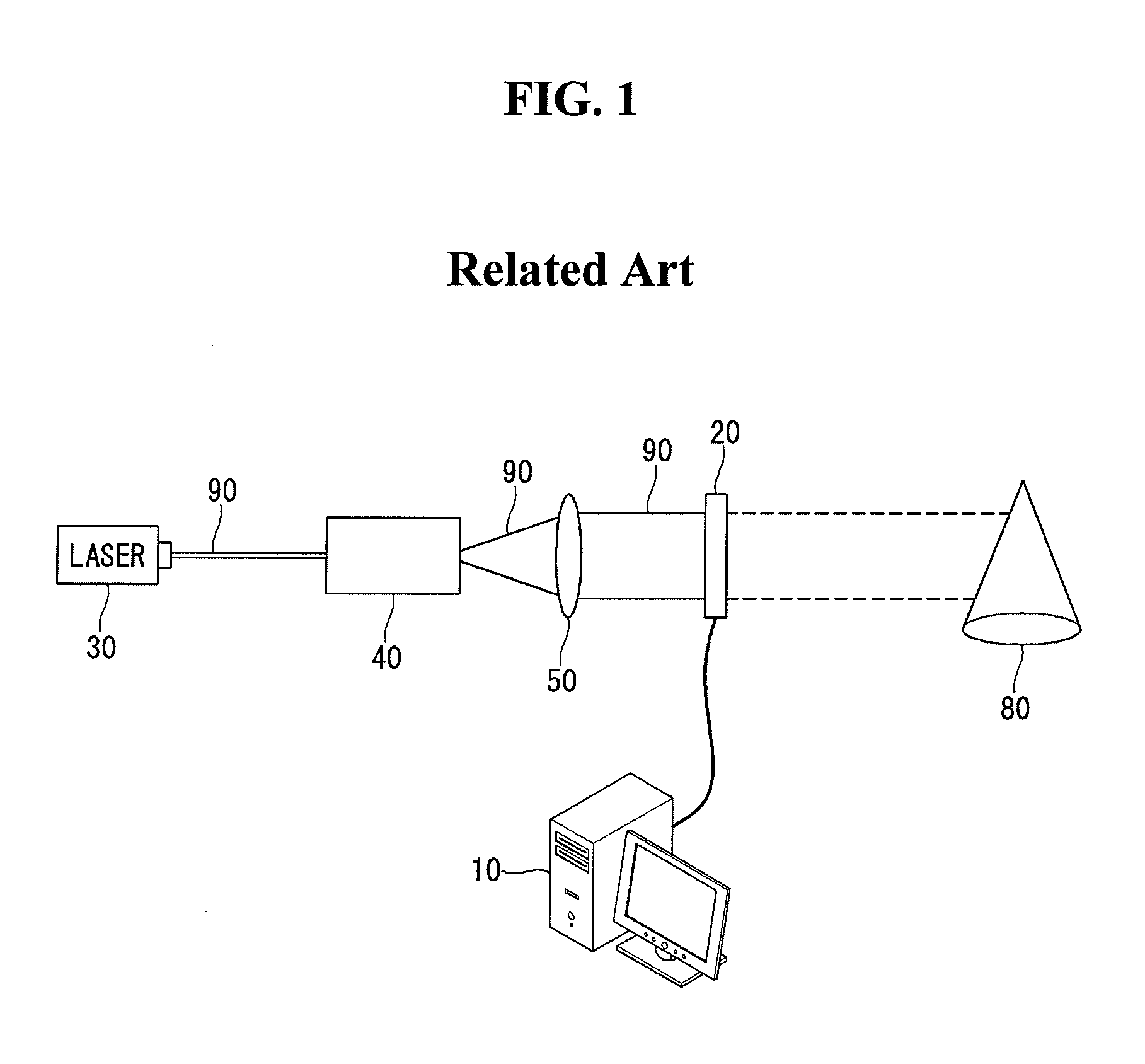
In case that this kind 3D display system is configured, it may have large volume and huge weight.
That is, the conventional arts for the holography type 3D display system are not adequate to apply to the thin, light and portable display systems which are recently required.
As combining two SLM, the system would be thicker and expensive than the system using one SLM.
Furthermore, it is hard to align these two SLMs and the method for driving two SLM in combination may be very complicated.

Method used


Image

  • Spatial light modulating panel using transmittive liquid crystal display panel and 3D display device using the same
  • Spatial light modulating panel using transmittive liquid crystal display panel and 3D display device using the same
  • Spatial light modulating panel using transmittive liquid crystal display panel and 3D display device using the same

Examples


Embodiment Construction

[0030]Referring to attached figures, we will explain preferred embodiments of the present disclosure. Like reference numerals designate like elements throughout the detailed description. However, the present disclosure is not restricted by these embodiments but can be applied to various changes or modifications without changing the technical spirit. In the following embodiments, the names of the elements are selected by considering the easiness for explanation so that they may be different from actual names.

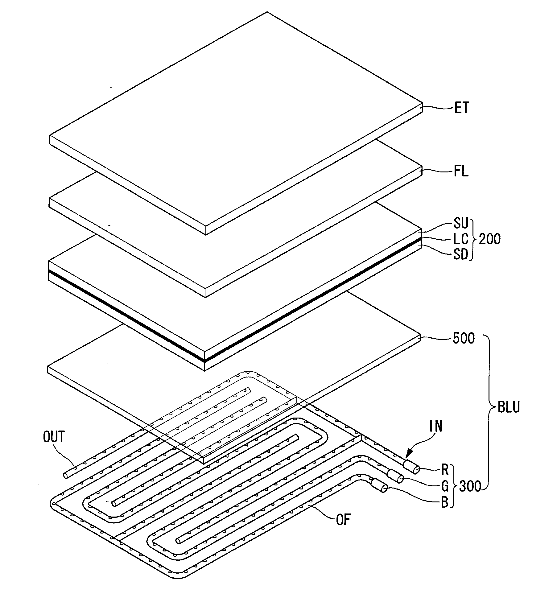
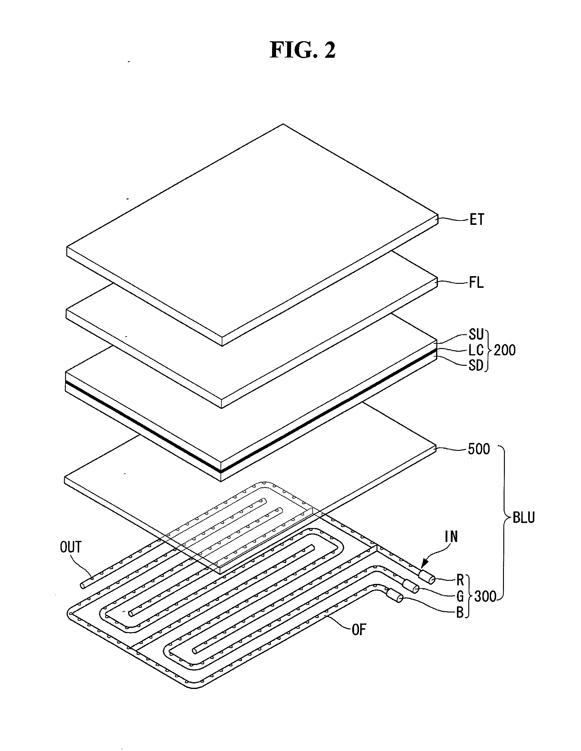
[0031]Referring to FIG. 2, we will explain a thin flat type holography 3D display device using a transmittive liquid crystal display used as the space light modulator according to the present disclosure. FIG. 2 is a structural drawing illustrating the digital holography image / video display device using a transmittive liquid crystal display device according to the present disclosure.

[0032]The holography 3D display device according to the present disclosure comprises a SLM 200 made...


PUM

PropertyMeasurementUnit
phaseaaaaaaaaaa
birefringenceaaaaaaaaaa
thicknessaaaaaaaaaa

Abstract

The present disclosure relates to a spatial light modulating panel using a transitive liquid crystal display panel and a three-dimensional display device using the same. The present disclosure suggests a spatial light modulator comprising: a plurality of pixels arrayed in a matrix manner; and a liquid crystal layer configured to modulate phase of an incident light passing through the each pixel, respectively. The spatial light modulator and the 3D display using the same according to the present disclosure provides thin flat type display system having the easy and simple structure and the low manufacturing cost.

Description

[0001]This application claims the benefit of Korean Patent Application No. 10-2011-0119727 filed on Nov. 16, 2011, which is incorporated herein by reference for all purposes as if fully set forth herein.BACKGROUND OF THE INVENTION[0002]1. Field of the Invention[0003]The present disclosure relates to a spatial light modulating panel using a transitive liquid crystal display panel and a three-dimensional (or 3D) display device using the same. Especially, the present disclosure relates to a spatial light modulating panel using a transitive liquid crystal display panel applied to the holography type 3D display and a 3D display device using the same.[0004]2. Discussion of the Related Art[0005]Recently, many technologies and researches for making and reproducing the 3D (Three Dimensional) image / video are actively developed. As the media relating to the 3D image / video is a new concept media for virtual reality, it can improve the visual information better, and it will lead the next generat...

Claims


Application Information

Patent Timeline
Patent Type & Authority Applications(United States)
IPC IPC(8): G03H1/22G02F1/13G02B30/25
CPCG02B27/0093A61B3/113G02F1/1393G02F2203/50G02B6/001G03H2225/61G03H1/2294G02B27/22G03H2001/0858G03H2225/32G03H2225/60G02F1/1313G03H1/04
Inventor YOON, MINSUNGKIM, SUNWOOSHIN, MINYOUNG
Owner LG DISPLAY CO LTD
Why Eureka
Eureka Blog
Learn More