Piezoelectric driving module for lens

a technology of piezoelectric motor and lens module, which is applied in the direction of mountings, optics, instruments, etc., can solve the problems of increasing the size, complexity and cost of the entire mechanical structure, complicated assembly process, and high power consumption, and achieve the effect of reducing the gravity-induced speed difference of the lens modul

Active Publication Date: 2013-05-16
TDK TAIWAN
View PDF1 Cites 9 Cited by
  • Summary
  • Abstract
  • Description
  • Claims
  • Application Information

AI Technical Summary

Benefits of technology

[0008]The primary objective of the present invention is to provide a piezoelectric driving module for lens, wherein a piezo member is provided on a housing and configured for driving a lens module into axial movement within the housing, and wherein a predetermined frictional force generated between a rubbing element and the lens module helps reduce a gravity-induced speed difference of the lens module while the lens module is being zoomed or focused.

Problems solved by technology

These driving and transmission elements not only increase the size, complexity, and cost of the entire mechanical structure, but also lead to a complicated assembly process, high power consumption, and consequently a high selling price.
As a result, a speed difference occurs when the lens module is moved back and forth in a zooming or focusing process.
Such a large speed difference increases not only the difficulty in precisely controlling the position of the lens module, but also the circuit complexity and cost of the positioning module employed.

Method used


Image

  • Piezoelectric driving module for lens
  • Piezoelectric driving module for lens
  • Piezoelectric driving module for lens

Examples


Embodiment Construction

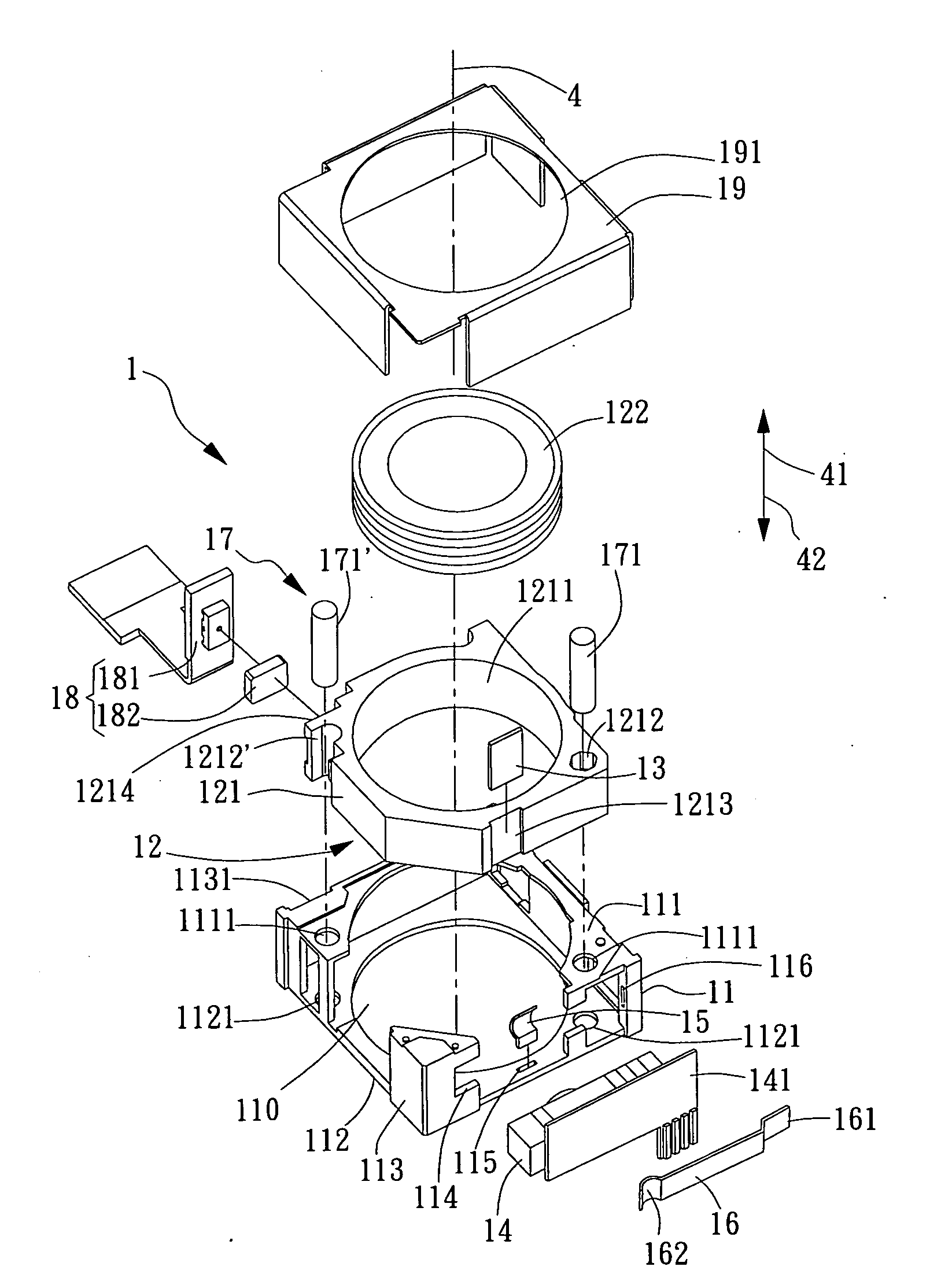
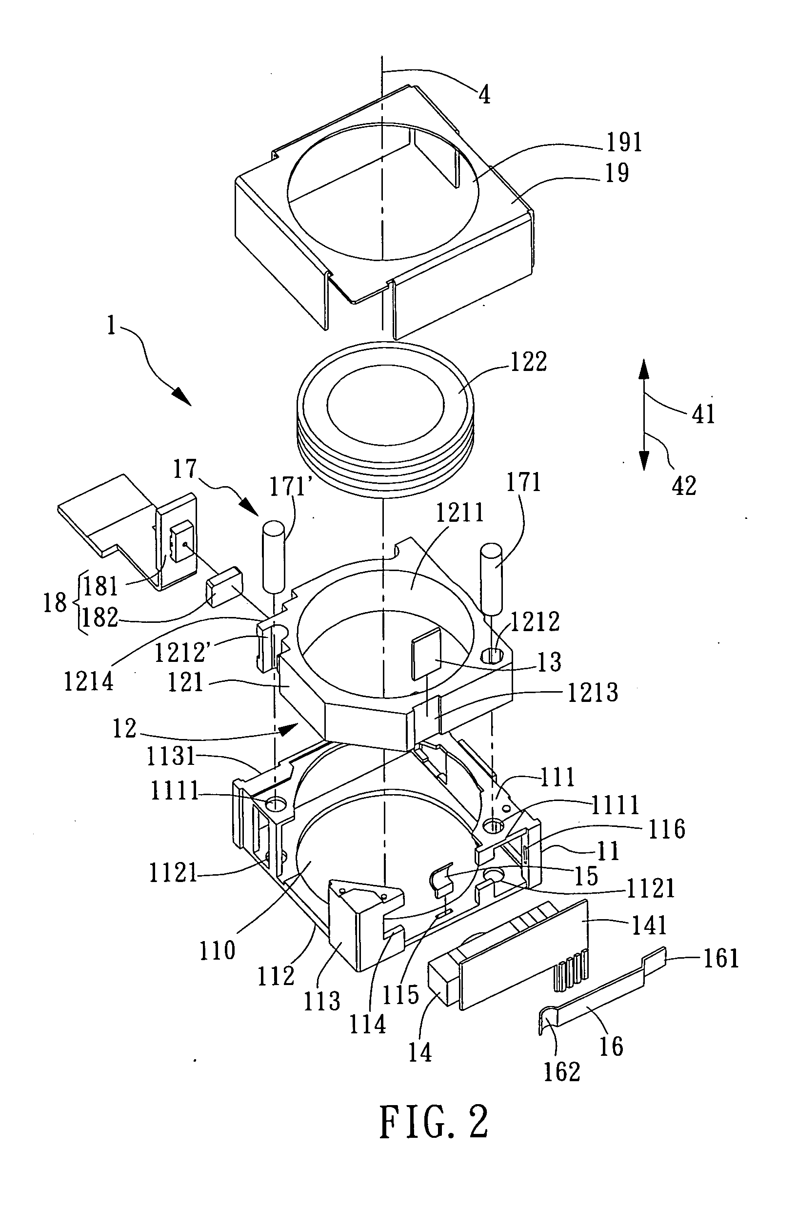
[0028]Herein, a piezo member refers to a component formed of a piezoelectric material whose converse piezoelectric effect is put to practical use. More specifically, a voltage is applied to the piezoelectric material of a piezo member to deform and hence cause displacement of the piezoelectric material. The movement of a strained piezoelectric material can be generally divided into: 1. linear longitudinal movement, which is typical of single-plate or laminated piezo members; and 2. curved lateral movement, which is typical of unimorphs and bimorphs. Piezo members designed for linear longitudinal movement advantageously feature high rigidity and a large axial pushing force, while those designed for curved lateral movement provide relatively large displacements.

[0029]The piezo member used in the piezoelectric driving module for lens of the present invention is an actuating element generally known as a piezoelectric motor. The piezoelectric motor in the present invention is formed of a...


PUM


Abstract

A piezoelectric driving module for lens, which defines a photographic optical axis and includes a housing, a driven object (e.g., a lens module), a piezo member, and a rubbing element. The piezo member and the rubbing element are provided in the housing and located on two lateral sides of the driven object respectively. The piezo member drives the driven object by friction so that the driven object can be moved along the photographic optical axis until focused. Meanwhile, a predetermined frictional force is generated between the rubbing element and the driven object to reduce a gravity-induced speed difference between forward and backward movements of the driven object along the photographic optical axis.

Description

BACKGROUND OF THE INVENTION[0001]1. Field of the Invention[0002]The present invention relates to a lens driving module and, more particularly, to a piezoelectric driving module with a piezoelectric motor for driving a lens module, wherein the lens module, when so driven during a zooming or focusing process, is rubbed against a rubbing element so that a predetermined frictional force is generated therebetween to reduce a gravity-induced speed difference of the lens module.[0003]2. Description of the Prior Art[0004]Please refer to FIG. 1 for an exploded perspective view of a conventional focusing lens unit which includes a focusing mechanism 9 based on mechanical transmission. In order to drive the supporting seat 93 mounted with the lens set 92, the focusing mechanism 9 uses a costly precision driving element 91 (e.g., a step motor, a supersonic motor, etc.) and a large number of transmission elements. These driving and transmission elements not only increase the size, complexity, an...

Claims


Application Information

Patent Timeline
Patent Type & Authority Applications(United States)
IPC IPC(8): G02B7/04
CPCG02B7/102G02B7/08
Inventor HU, CHAO CHANGCHEN, SHU SHAN
Owner TDK TAIWAN
Why Eureka
Try Eureka