DC pre-charge circuit

a dc bus and circuit technology, applied in the field of electric drives, can solve the problems of increasing the overall size of each drive, affecting the operation of the motor drive, and affecting the operation of the starter device,

Active Publication Date: 2013-05-16
ROCKWELL AUTOMATION TECH
View PDF3 Cites 37 Cited by
  • Summary
  • Abstract
  • Description
  • Claims
  • Application Information

AI Technical Summary

Problems solved by technology

Sometimes during operation of a motor drive system, and particularly during start-up, high levels of in-rush current may be received by a motor drive in the motor drive system, which may cause various adverse affects to the motor drive.
However, such configurations may result in significant power loss through the diode and may not be used to isolate the drive from the common DC bus.
Furthermore, each of the above described pre-charge circuit configurations and techniques involve using one or more circuit breakers to isolate or disconnect a drive from the common DC bus, which increases the overall size of each drive.

Method used


Image

  • DC pre-charge circuit
  • DC pre-charge circuit
  • DC pre-charge circuit

Examples


Embodiment Construction

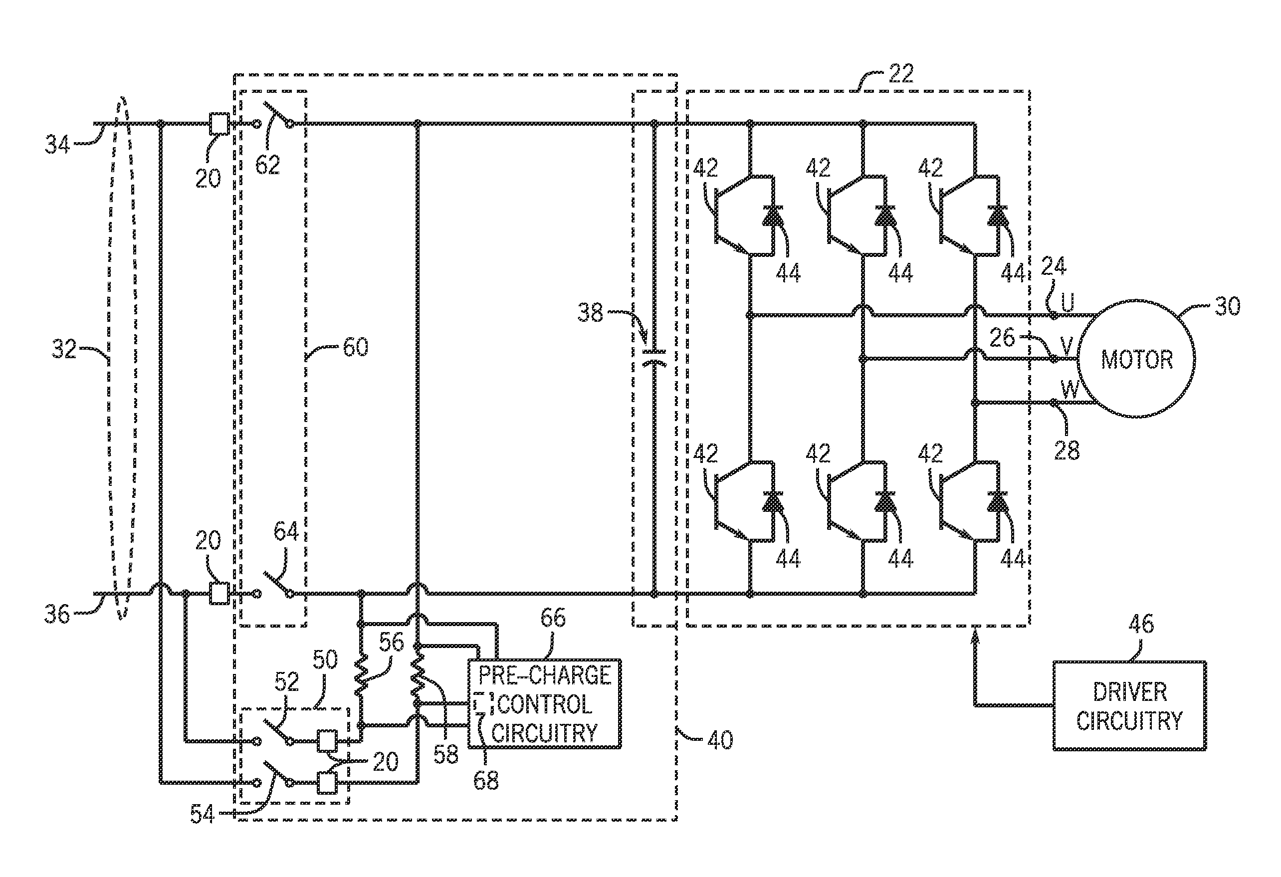
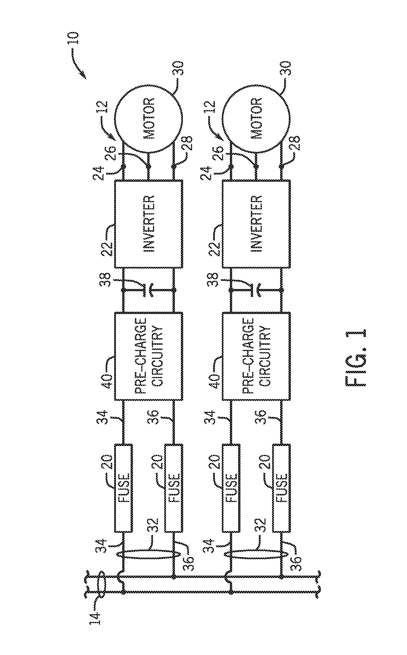
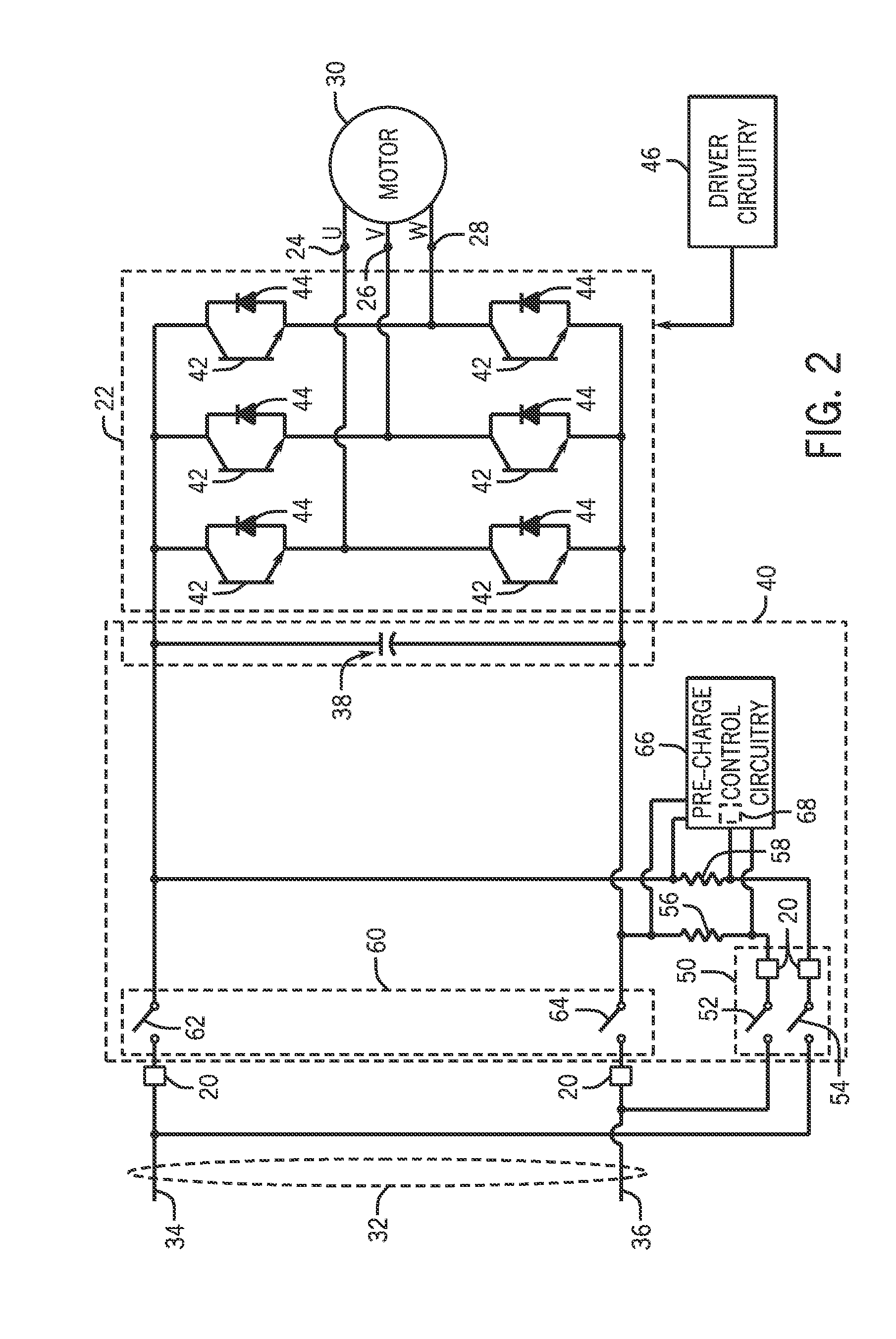
[0016]Systems and methods of the present invention are related to pre-charging a DC bus on a motor drive in a motor drive system. During operation of a motor drive system, and particularly during start-up, motor drive circuitry (e.g., inverter, capacitors) may draw high levels of in-rush current while charging power-conditioning capacitors associated with the motor drive. Typically, motor drive configurations include pre-charge circuitry, which applies a smaller initial current to the DC bus of the motor drive prior to starting the motor drive. The smaller current provided to the DC bus may charge DC capacitors (i.e., power-conditioning capacitors) that may be coupled to the DC bus. Pre-charging the capacitors with the smaller initial current may protect the capacitors from possible damage that may be caused by the high levels of in-rush current during start-up. Some existing pre-charge techniques may not be suitable for addressing line sags (e.g., drops in the DC bus voltage) which...


PUM


Abstract

Systems and methods are provided for pre-charging the DC bus on a motor drive. Pre-charging techniques involve pre-charge circuitry including a manual switch, an automatic switch, and pre-charge control circuitry to switch the automatic switch between pre-charge and pre-charge bypass modes in response to an initialized pre-charge operation, input voltage sags, and so forth. In some embodiments, the pre-charge operation may be initialized by switching the manual switch closed. In some embodiments, the pre-charge operation may also be initialized by a detected voltage sag on the DC bus. The pre-charge circuitry may also be configured to disconnect to isolate a motor drive from the common DC bus under certain fault conditions.

Description

CROSS-REFERENCE TO RELATED APPLICATIONS[0001]This application claims the benefit of U.S. Provisional Application No. 61 / 559,650, filed Nov. 14, 2011.BACKGROUND[0002]The invention relates generally to the field of electrical drives. More particularly, the invention relates to techniques for pre-charging a direct current (DC) bus in a power drive.[0003]In the field of power electronic devices, a wide range of circuitry is known and currently available for converting, producing, and applying power to loads. Depending upon the application, motor drive systems may include circuitry that converts incoming power from one form to another as needed by the load. In a typical drive system, for example, a rectifier converts alternating current (AC) power (such as from a utility grid or generator) to direct current (DC) power. Inverter circuitry can then convert the DC signal into an AC signal of a particular frequency desired for driving a motor at a particular speed. The inverter circuitry typ...

Claims


Application Information

Patent Timeline
Patent Type & Authority Applications(United States)
IPC IPC(8): H02M7/537
CPCH02M7/48H02H7/09H02P6/28H02M7/537H02P6/20
Inventor WEISS, BRUCE W.BUSSE, DOYLE F.KEEGAN, JEREMY J.WEI, LIXIANGLOTH, MICHAEL W.TALLAM, RANGARAJAN M.PATEL, YOGESH
Owner ROCKWELL AUTOMATION TECH
Why Eureka
Try Eureka