Magnetic-Field Measurement Device

a magnetic field and measurement device technology, applied in the direction of measurement devices, instruments, scientific instruments, etc., can solve the problems of bf separation becoming a significant factor of hampering speedy inspection, bringing about a limit, and bf separation becoming a significant factor of bf separation, etc., to achieve the effect of stably measuring an antigen-antibody and simple apparatus configuration

Inactive Publication Date: 2013-05-16
HITACHI LTD
View PDF4 Cites 12 Cited by
  • Summary
  • Abstract
  • Description
  • Claims
  • Application Information

AI Technical Summary

Benefits of technology

[0031]According to the present invention, there is realized an immunoassay system which can stably measure an antigen-antibody reaction without magnetic shielding and by a simple apparatus configuration.

Problems solved by technology

In recent years, despite high needs for detecting an extremely small antigen-antibody reaction with a high sensitivity at a high speed, there is brought about a limit since a solid phase method is used as a cleaning step that is referred to as BF (Bound / Free) separation.
The BF separation takes time and labor, and therefore, the BF separation becomes a significant factor of hampering speedy inspection.

Method used


Image

  • Magnetic-Field Measurement Device
  • Magnetic-Field Measurement Device
  • Magnetic-Field Measurement Device

Examples


first embodiment

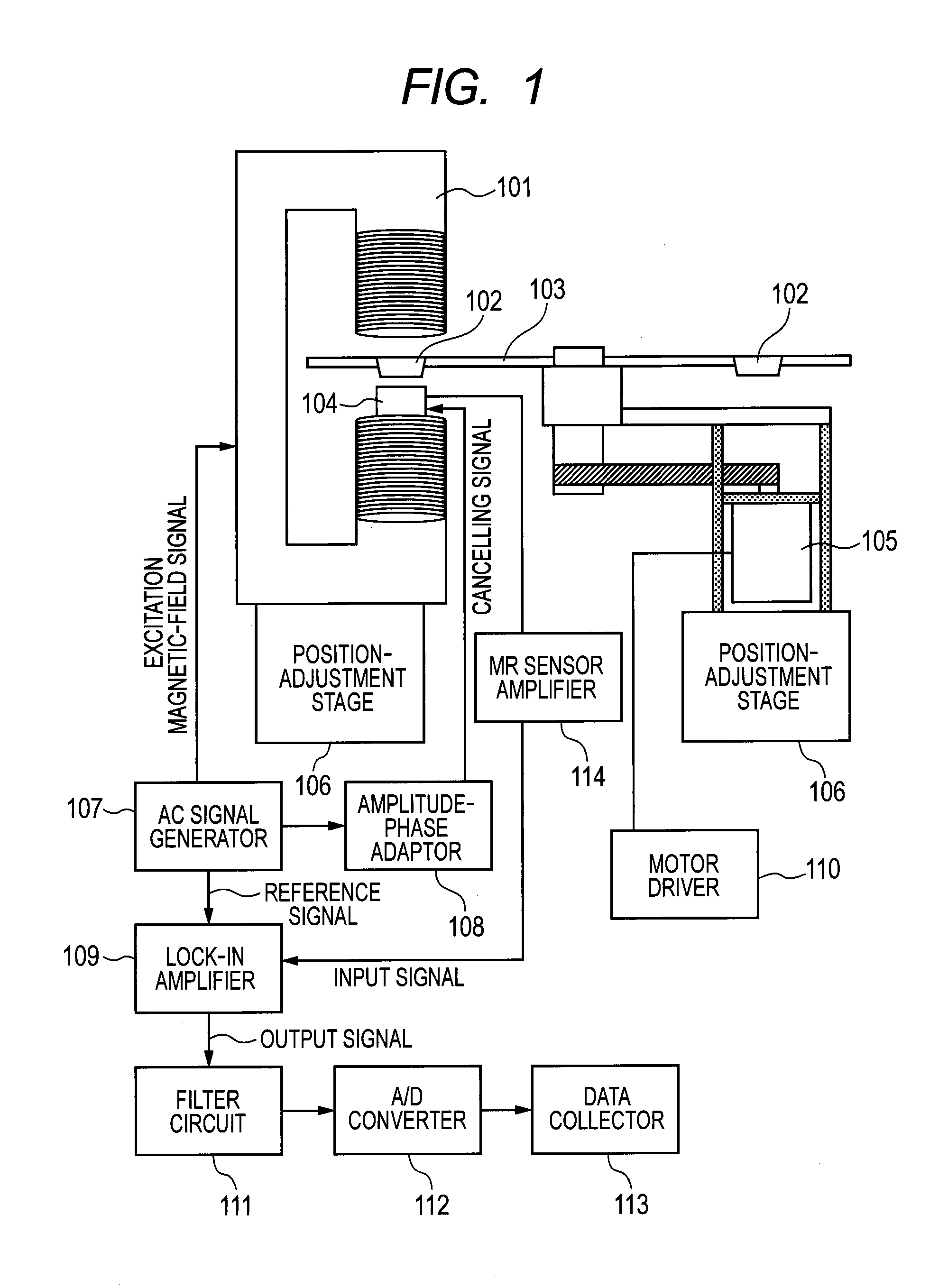
[0068]An explanation will be given of first embodiment of the present invention in reference to FIG. 1. An inspection sample is contained in an inspection vessel 102 included in the non-magnetic plate 103 as shown in FIG. 1. The non-magnetic plate 103 is rotated to move by a drive system configured by the DC motor 105. The inspection sample is magnetized by the AC magnetism from the excitation coil 101 by passing the non-magnetic plate 103 through the excitation coil 101 in rotating the non-magnetic plate 103. As shown in FIG. 1, the excitation coil 101 is of a Helmholtz coil type, and the inspection sample passes to traverse at a vicinity of a center between coils. The MR sensor 104 which measures a magnetism signal from the inspection sample is constructed by a structure integrated with the excitation coil 101. A system noise caused by a vibration can be reduced by integrating the excitation coil 101 and the MR sensor 104 in this way. According to the present embodiment, the non-m...

second embodiment

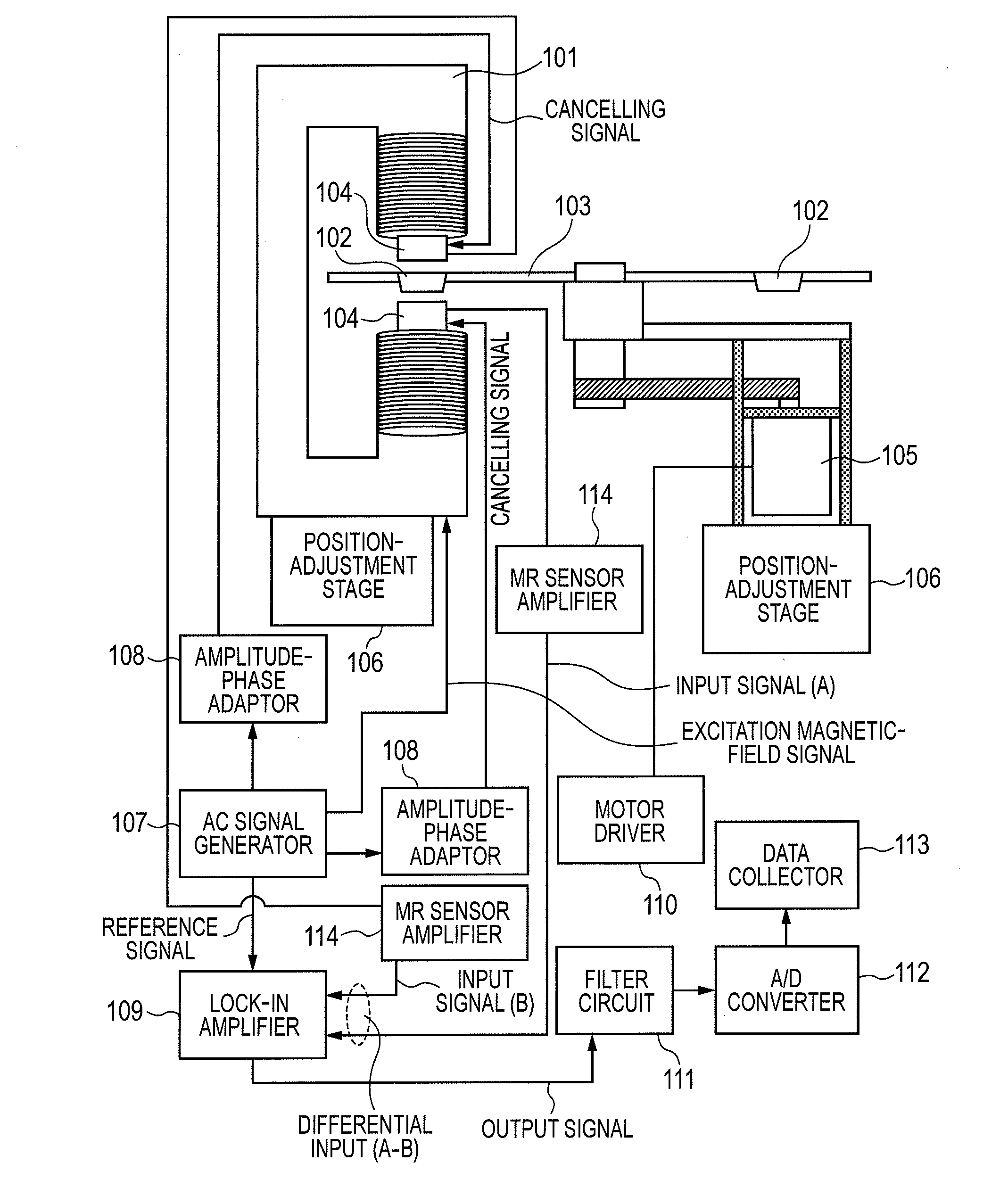
[0074]An explanation will be given of a second embodiment of the present invention in reference to FIG. 7. There is constructed a configuration of using two of the MR sensors 114 and interposing the inspection sample vessel by the respective MR sensors 114 as shown in FIG. 7. The inspection sample vessel 102 passes through the excitation coil 101 by rotating the non-magnetic plate 103 by using the drive unit configured by the DC motor 105 similar to the first embodiment. At that occasion, the inspection sample in the inspection sample vessel 102 is magnetized by the AC magnetism from the excitation coil 101 (FIG. 8A). Magnetism signals from the magnetized inspection sample are configured by dispersion type waveforms (waveforms having minimum values and maximum values) respectively inverted by the MR sensor 104 arranged at an upper portion of the inspection sample vessel 102 and the MR sensor 104 arranged at a lower portion thereof (FIG. 8B). Therefore, it can said that the magnetism...

third embodiment

[0076]A third embodiment of the present invention includes an optical type displacement sensor for monitoring a displacement between the MR sensor and the inspection sample vessel in the immunoassay apparatus described in the first embodiment or the second embodiment of the present invention. As shown in FIG. 11, the optical type displacement sensor 115 is arranged right below the inspection sample vessel 102 provided at the non-magnetic plate 103. A magnetism of a magnetism signal from the inspection sample is measured by the MR sensor 104, at the same time, a change in the displacement of the inspection sample vessel by bending the non-magnetic plate in rotating the non-magnetic plate is simultaneously measured by the optical type displacement sensor. Incidentally, despite the simultaneous measurement, the MR sensor and the optical type displacement sensor detect respectively separate pieces of information of the magnetism signal and the displacement of the inspection sample in vi...


PUM

PropertyMeasurementUnit
magnetic fieldaaaaaaaaaa
sizeaaaaaaaaaa

Abstract

The disclosed magnetic immunoassay device, which performs magnetic immunoassays using antigen-antibody reactions, can perform speedy immunoassays without bound/free separation in the test samples. The device is also practical, being capable of stable magnetism measurement without magnetic shielding. The disclosed magnetic immunoassay device is provided with: an excitation coil that uses an AC magnetic field to magnetize a test sample containing a magnetic marker; a magnetism sensor that measures magnetism in the test sample and outputs a magnetism signal; and a displacement sensor for detecting changes in the distance between the test sample and the magnetism sensor. By optimally setting the bandwidth of a lock-in amplifier, which detects changes in the phase of the magnetism signal outputted by the magnetism sensor, and the rotational speed produced by a drive system, which moves the test sample at low speeds, the impact of environment magnetic noise is reduced, and correcting the magnetism signal using distance information obtained from the displacement sensor allows stable magnetism measurement.

Description

TECHNICAL FIELD[0001]The present invention relates to a magnetic-field measurement device, for example, relates to an immunoassay technology which applies an AC magnetic field to a measurement sample that includes a small magnetic particle and detects an antigen-antibody reaction by a magnetic method.BACKGROUND ART[0002]An immunoreaction is widely used in various fields from a detection of a germ or a cancer cell in foods over to a detection of an environmental harmful substance causing allergy or the like. The immunoreaction is caused by coupling a measurement object substance (antigen) and an inspection reagent (antibody) which selectively couples with the antigen, and a kind and an amount of the antigen are measured from the coupling. In an inspection using such an immunoreaction, a marker is added to the antibody for using a reaction of coupling an antigen and antibody (antigen-antibody reaction). An optical marker is generally used for the marker, and the antigen-antibody react...

Claims


Application Information

Patent Timeline
Patent Type & Authority Applications(United States)
IPC IPC(8): G01N33/543
CPCG01N33/54333G01N27/745
Inventor KAWABATA, RYUZOMIZOGUCHI, TAKAKOTSUKAMOTO, AKIRAKANDORI, AKIHIKOYOSHIMURA, TOMOKO
Owner HITACHI LTD
Why Eureka
Try Eureka