Drive arrangement

a technology of driving arrangement and drive shaft, which is applied in the direction of electric propulsion mounting, transportation and packaging, gearing, etc., can solve problems such as problems such as the accommodation of motor vehicles, and achieve the effect of increasing the overall transmission ratio and high drive torqu

Inactive Publication Date: 2013-05-16
AUDI AG
View PDF9 Cites 25 Cited by
  • Summary
  • Abstract
  • Description
  • Claims
  • Application Information

AI Technical Summary

Benefits of technology

[0011]In a further advantageous embodiment of the invention, the rotor of the electric machine can output to the drive element of the differential via a first gear mechanism and the output elements of the differential can output to the offset output shafts or respectively flange shafts via intermediate shafts and second gear mechanisms. This achieves to further increase the overall transmission ratio between the electric machine and output to the output shafts or respectively, flange shafts or respectively the driven wheels of the motor vehicle at a structurally particularly compact construction which allows realizing high drive torques at adequate dimensions of the electric machine.
[0012]Advantageously, the first gear mechanism can be shiftable via a shift

Problems solved by technology

If the electric machine is to have a high torque or respectively a high

Method used


Image

  • Drive arrangement
  • Drive arrangement
  • Drive arrangement

Examples


Embodiment Construction

[0024]Throughout all the Figures, same or corresponding elements are generally indicated by same reference numerals. These depicted embodiments are to be understood as illustrative of the invention and not as limiting in any way. It should also be understood that the drawings are not necessarily to scale and that the embodiments are sometimes illustrated by graphic symbols, phantom lines, diagrammatic representations and fragmentary views. In certain instances, details which are not necessary for an understanding of the present invention or which render other details difficult to perceive may have been omitted.

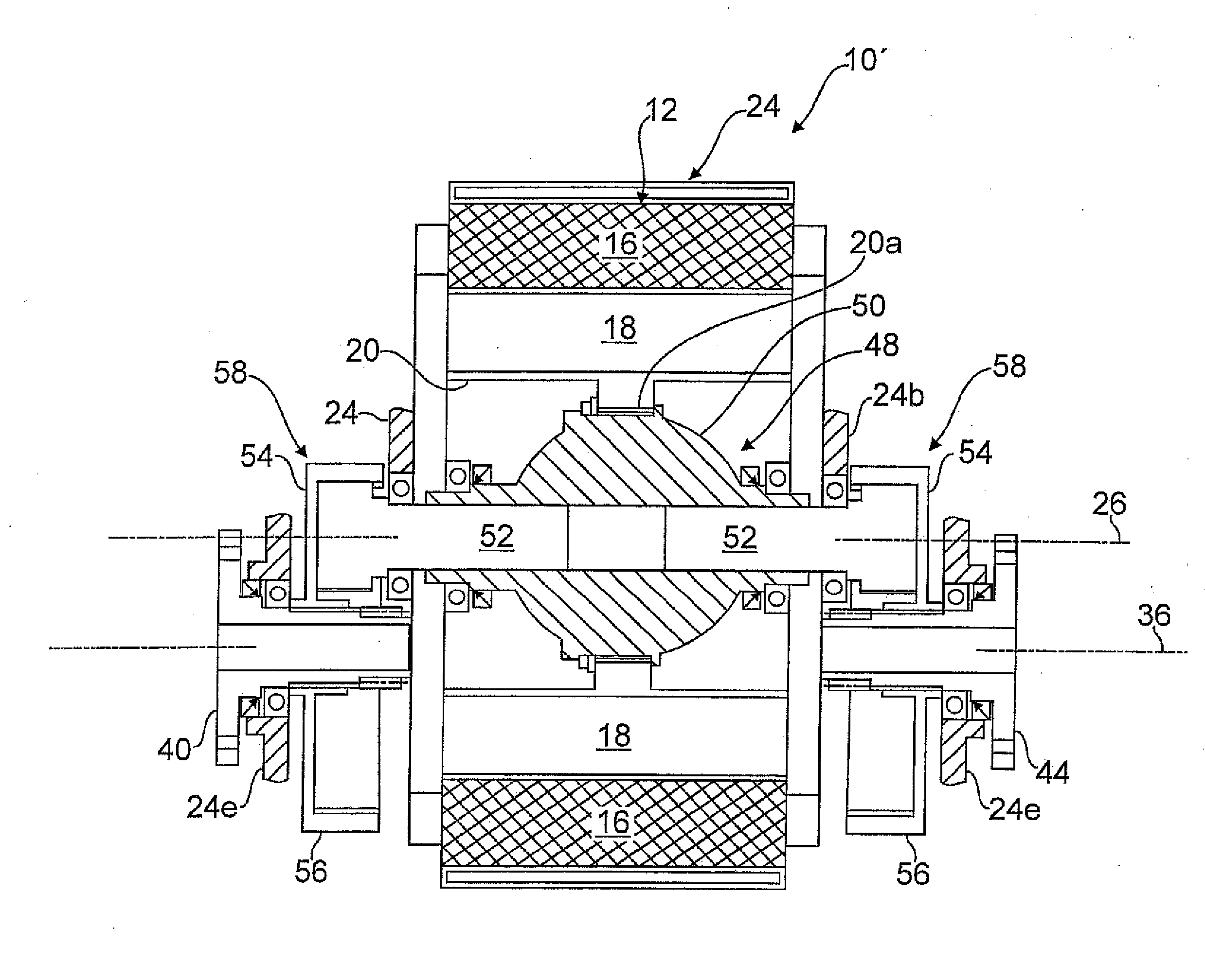
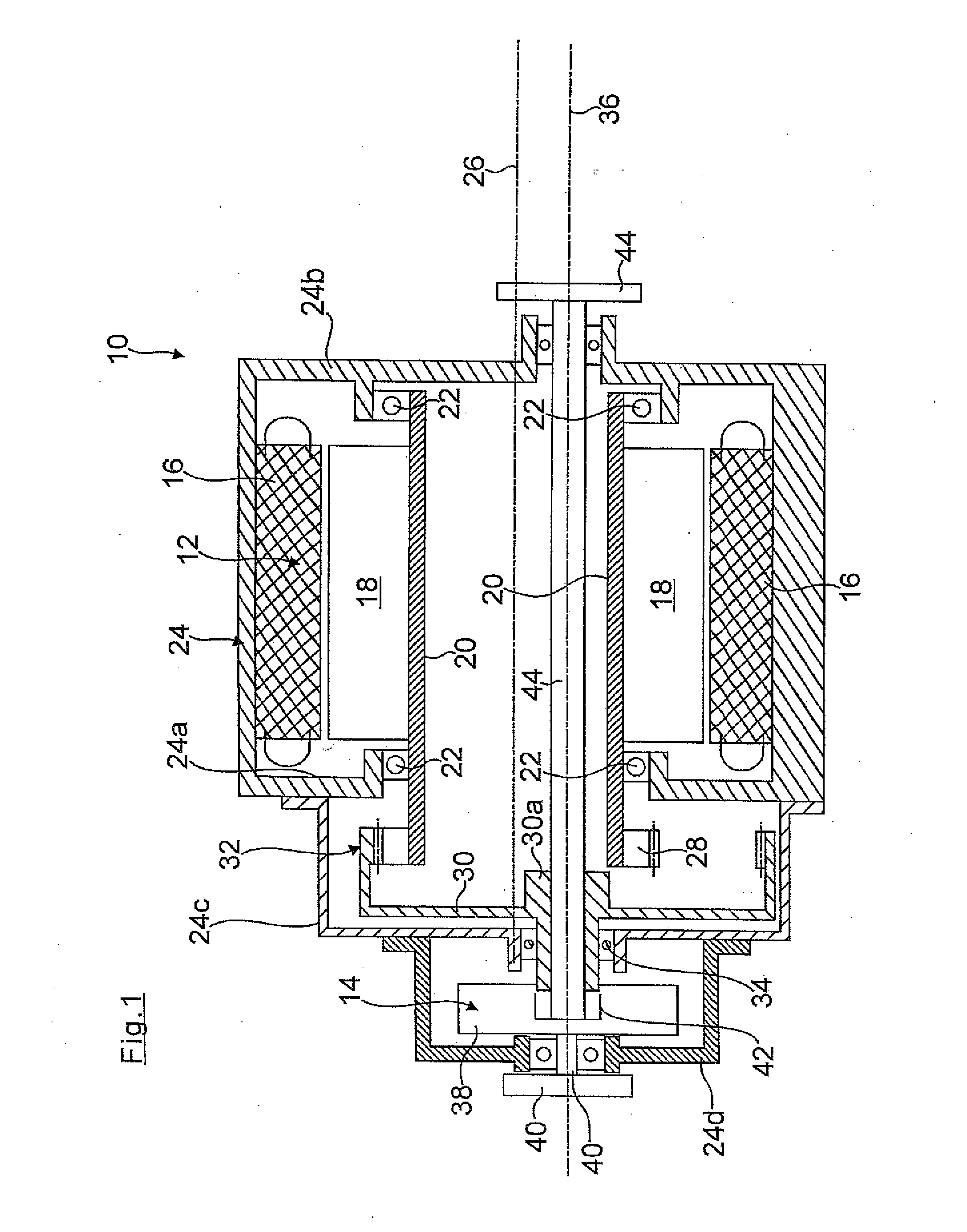
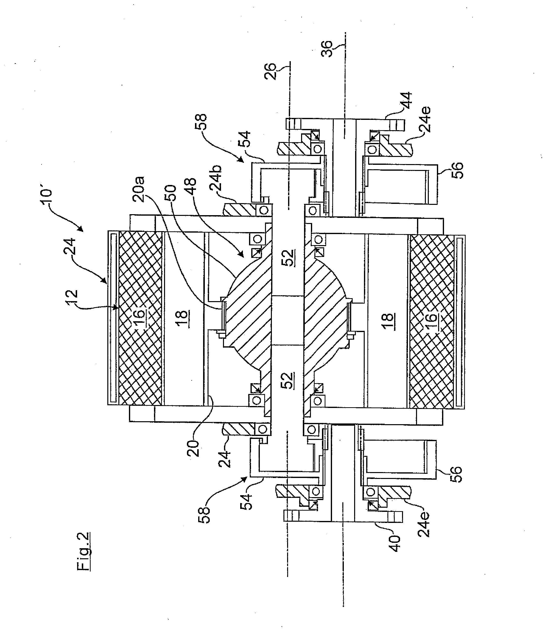
[0025]Turning now to the drawing, and in particular to FIG. 1, there is shown a schematic illustration of a first drive arrangement for an electrically driven axle (for example a front axle or rear axle) of a motor vehicle designated 10, which is substantially formed by an electric machine 12 and a differential 14.

[0026]The driving electric machine 12, which can be operated du...


PUM


Abstract

In a drive arrangement for wheels of a motor vehicle which are driven by means of an electric machine via a differential, the electric machine includes a rotor and a stator and drives a drive element of the differential whose output shafts output to the wheels of the motor vehicle. In order to achieve a structurally compact construction which enables favorable transmission ratios the rotor outputs to the drive element of the differential and that by interposing a gear mechanism, the drive element and/or the output shafts are supported offset to the rotation axis of the rotor.

Description

CROSS-REFERENCES TO RELATED APPLICATIONS[0001]This application claims the priority of German Patent Application, Serial No. 10 2011 100 817.2, filed May 6, 2011, pursuant to 35 U.S.C. 119(a)-(d), the disclosure of which is incorporated herein by reference.BACKGROUND OF THE INVENTION[0002]The present invention relates to a drive arrangement for wheels of a motor vehicle.[0003]The following discussion of related art is provided to assist the reader in understanding the advantages of the invention, and is not to be construed as an admission that this related art is prior art to this invention.[0004]In electrically driven motor vehicles or hybrid drives, it is know to drive an axle of the motor vehicle by means of an electromotor or an electric machine (also shiftable to function as generator during braking) via a customary differential. If the electric machine is to have a high torque or respectively a high driving power, the accommodation in the motor vehicle can pose problems.[0005]I...

Claims


Application Information

Patent Timeline
IPC IPC(8): B60K17/16
CPCB60K1/00B60K17/16B60K2001/001
Inventor MARKL, JOHANN
Owner AUDI AG
Why Eureka
Try Eureka