Signal transfer circuit

Active Publication Date: 2013-05-16
OLYMPUS CORP
View PDF5 Cites 4 Cited by
  • Summary
  • Abstract
  • Description
  • Claims
  • Application Information

AI Technical Summary

Benefits of technology

The present invention is a signal transfer circuit that can improve the timing between an arbiter and a bus master that follow a protocol for access. The invention helps to overcome the limitations of the timing of the input / output signal so that the two components can work together more efficiently.

Problems solved by technology

Thus, it is difficult to increase the number of embedded bus masters for a high-performance system LSI in the system LSI in accordance with the related art.
If the layout positions of the arbiter and the bus master are away from each other, a wiring length of a signal to be input and output between the arbiter and the bus master becomes long and a delay time of wiring increases.
Thereby, there is a problem in that a time available for control or a data output that is necessary to be performed before the next clock cycle within the bus master becomes short and the control or the data output does not end before the next clock cycle, that is, the protocol is not conformed.
In addition, it is difficult to speed up an operation clock for a high-performance system LSI in the system LSI in accordance with the related art.
Thus, there is a problem in that it may be impossible to speed up an operation clock to a certain extent or more to keep the protocol when a delay time of a signal by the number of logical stages of the request generation circuit 921 (or the request generation circuit 931), the data control circuit 923, or the data latch control circuit 933 is considered.

Method used


Image

  • Signal transfer circuit
  • Signal transfer circuit
  • Signal transfer circuit

Examples


Embodiment Construction

[0057]The present invention will be now described herein with reference to illustrative preferred embodiments. Those skilled in the art will recognize that many alternative preferred embodiments can be accomplished using the teaching of the present invention and that the present invention is not limited to the preferred embodiments illustrated for explanatory purpose.

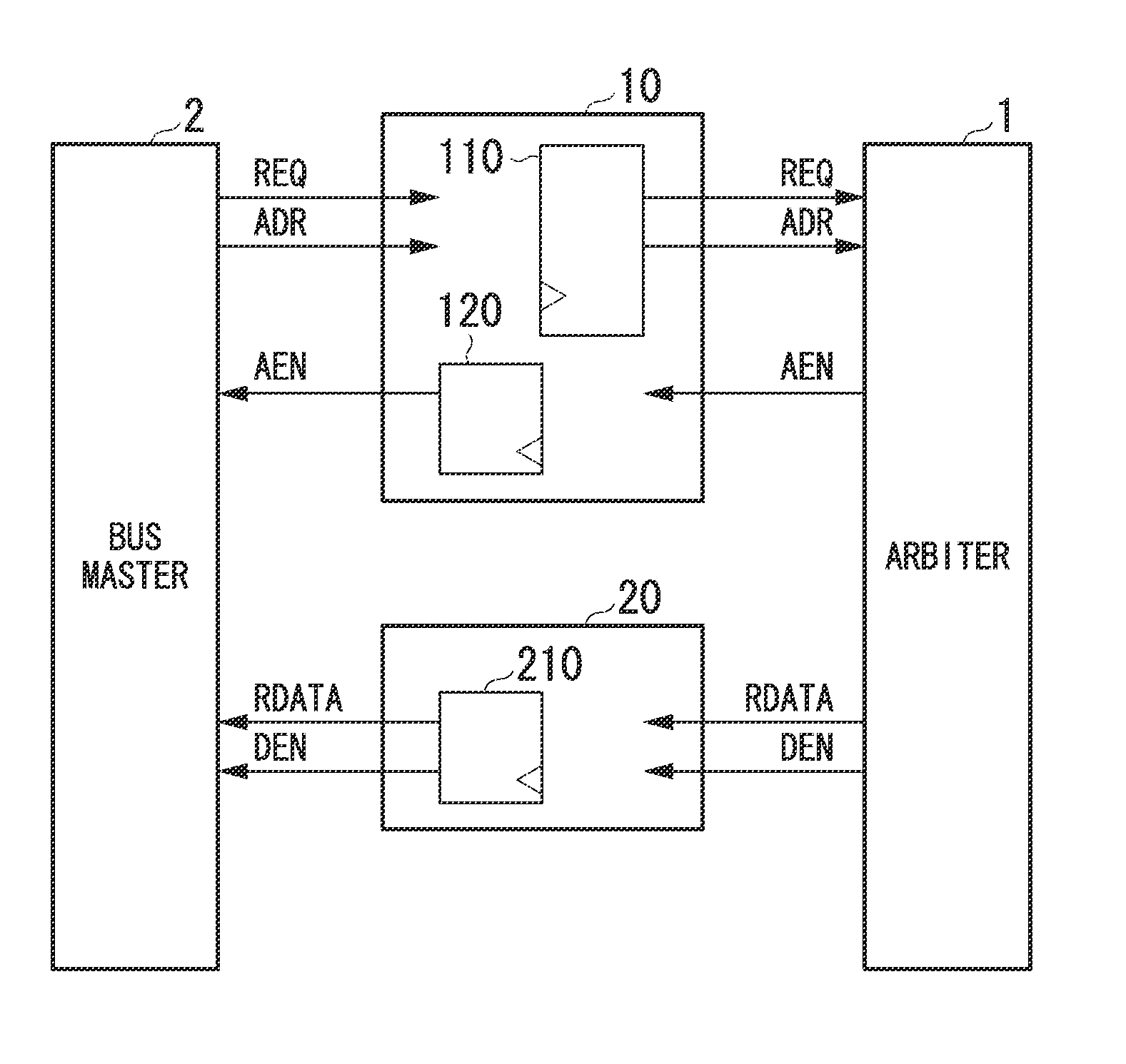
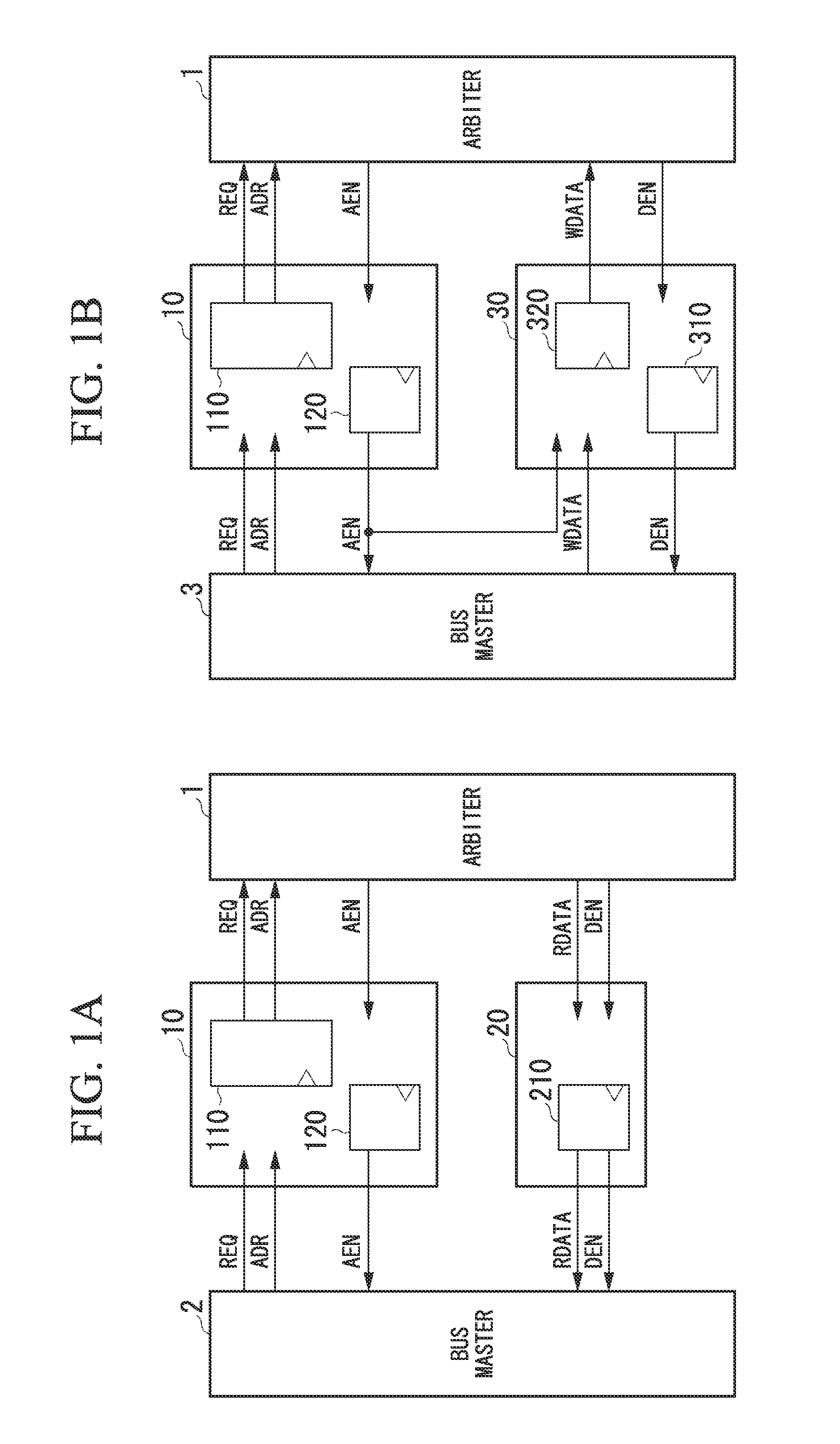
[0058]FIGS. 1A and 1B are block diagrams illustrating basic configurations of a signal transfer circuit in accordance with a first preferred embodiment of the present invention. FIGS. 1A and 1B illustrate basic concepts of the signal transfer circuit in accordance with the first preferred embodiment. As illustrated in FIGS. 1A and 1B, the signal transfer circuit in accordance with the first preferred embodiment of the present invention is inserted between an arbiter and a bus master. The signal transfer circuit is a circuit that transfers (relays) a signal to be input / output between the arbiter and the bus master. At th...


PUM


Abstract

A signal transfer circuit comprising a control signal transfer unit configured to output an access request output signal and a memory address output signal to the arbiter after timings of the access request input signal of the access request and the memory address input signal input from the bus master have been adjusted, and output an access permission output signal, and a data signal transfer unit configured to output each data output signal to the corresponding bus master or the arbiter after a timing of each data input signal of the access request input from the arbiter or the bus master is adjusted, and output a data validity period output signal to the bus master after a timing of a data validity period input signal indicating a period in which each data is valid in the access request input from the arbiter is adjusted.

Description

BACKGROUND OF THE INVENTION[0001]1. Field of the Invention[0002]The present invention relates to a signal transfer circuit.[0003]Priority is claimed on Japanese Patent Application No. 2011-250684, filed Nov. 16, 2011, the content of which is incorporated herein by reference.[0004]2. Description of the Related Art[0005]All patents, patent applications, patent publications, scientific articles, and the like, which will hereinafter be cited or identified in the present application, will hereby be incorporated by reference in their entirety in order to describe more fully the state of the art to which the present invention pertains.[0006]In many system large-scale integrations (LSIs) mounted on image processing apparatuses such as a still-image camera, a moving-image camera, a medical endoscope camera, and an industrial endoscope camera, a plurality of embedded processing blocks (hereinafter referred to as “bus masters”) share one connected dynamic random access memory (DRAM). In the sy...

Claims


Application Information

Patent Timeline
IPC IPC(8): G06F13/00
CPCG06F13/1605G06F13/00G06F13/362
Inventor NAKAZONO, KEISUKESHIMAMURA, MASAMITANAKA, YOSHINOBUUENO, AKIRA
Owner OLYMPUS CORP
Why Eureka
Try Eureka