Combined air, water and road vehicle

a combined air and road vehicle technology, applied in the direction of convertible aircraft, aircraft components, convertible vehicles, etc., can solve the problems of unsolved one-person solutions, unresolved road transportation legal or impractical, and difficulty in fitting one-person solutions into a vehicle only 2.55 m wide, so as to reduce the risk of mechanical failure, reduce the risk of confusion of controls, and reduce the stall speed

Active Publication Date: 2013-05-23
FLECK FITNESS CONCEPTS
View PDF32 Cites 75 Cited by
  • Summary
  • Abstract
  • Description
  • Claims
  • Application Information

AI Technical Summary

Benefits of technology

[0064]II). The purpose in regard to safety is to provide a). a strong but light frame, b). a strong wing spar locking mechanism, c). shielding of occupants via bumper bar and crunch zone from front-end road collisions, d). shielding of pedestrians / swimmers from the airscrew on all sides in all configurations, e). a low stall speed, f). gentle stalling characteristics, g). minimised risk of mechanical failure by having a minimum number of moving parts, h). separation of aircraft and automobile steering to eliminate risk of confusion of controls, i). centralisation of all heavy items (motor, occupants, etc.) to minimise risks associated with disbalance, j). large, side-entry doors for quick and easy emergency exit, k). inoperability of all items (even unintentionally) when they are not in use, l). multiple inflatable bladder-chambers such that landing on water remains possible despite deflation of any one chamber, m). shielding of the marine propeller from swimmers frontally and laterally and n). mounting of the marine propeller such that it poses no danger to airworthiness if accidentally extended in flight.
[0065]III). The purpose in regard to efficiency is to a). i). minimise wind resistance by 1). streamlining the fuselages, glider-like, 2). almost entirely enclosing the four large wheels within the fuselage and 3). retracting the wheel tips, ii). centralise heavy items to reduce trim requirements, iii). use only one motor for all modes of transportation to reduce weight, thereby increasing speed and lowering fuel consumption, b). simplify the structure with a small number of moving parts and centralise the main components to lower production and repair costs, c). optimise boat performance and stability by having two hulls and d). optimise marine propeller power delivery by placing the marine propeller near the centre of gravity.
[0066]IV). Practicality: The purpose in regard to practicality is to a). have just one vehicle for flying, driving and boating, b). have the vehicle conform to parking spot and garage size limitations as they apply to automobiles, c). enable comfortable road operation by having four independently suspended, standard-sized car wheels, d). provide scope of use beyond individual, short haul or recreational transport by providing seats for two occupants, e). reduce the noise footprint on the ground by locating the motor between the fuselages and above the aircraft, f). allow convenient, automated conversion between the various configurations g). provide a single lever for simultaneous steering conversion, transconfigurational power-transfer, mirror deployment, wing-locking and conversion of lighting wiring h). allow convenient engine management by employing one single lever combining control of automatic transmission, throttle, propeller pitch and wing-extension, i). provide seating comfort by including standard-size head and legroom together with bulges on the sides of each fuselage at elbow height for lateral space, j). provide ease of access by having standard size car doors at standard car height, k). provide familiarity through standard layouts and apportionments (i.e. high-winged, non-tail-dragger aircraft; four-wheel, steering-wheeled car, etc.) and l). provide increased cross-wing landing capabilities by having the wingtips well above the ground.

Problems solved by technology

Whereas almost all winged aircraft and most seaplanes have wheels and steering for taxiing on land, it is primarily their wingspan which makes them illegal or impractical for road transport.
Because of these major (and other minor) factors, a practical combined land / air vehicle (“flying car”) for everyday use has remained an unsolved technical problem for over 100 years.
But even a one-person solution is hard to fit into a vehicle only 2.55 m wide.
For this reason, almost half the known art dispenses with conventional wings and merely employs jets, fans or rotors, making it expensive, loud and therefore largely impractical.
The construction of roadable aircraft with integrated wings is far more difficult.
No known roadable rotorcraft art employs twin cabins / fuselages.
However, neither qualifies as a modular roadable aircraft.
The problem was; there was no cross-bar or wing under which to mount two forward wheels on the standard, monoplane, single-hulled aircraft of the time.
And extra struts and spats would have incurred more drag than the large, central wheel .
The only appreciable disadvantage of twin fuselages is that the occupants don't sit directly next to each other.
None has integrated or automatically deploying floats which are stowed to reduce drag.
The lack of such art is likely due to the contradictory nature of combining a swing-wing with a twin fuselage.
Furthermore, where just one central pivot is used, spar stubs which extend inward beyond the pivot (as in the instant art) cannot be employed because they'd block each other.
The resulting potential for confusion would increase the risk of accident.
If all 4 pedals were mounted next to each other, confusion would also exist and space issues would emerge). b).
Accidental use of controls should be impossible when they are not in use.

Method used


Image

  • Combined air, water and road vehicle
  • Combined air, water and road vehicle
  • Combined air, water and road vehicle

Examples


Embodiment Construction

[0143](a Reference Key Denoting the Terms Used Herein is Found at the End of this Section)

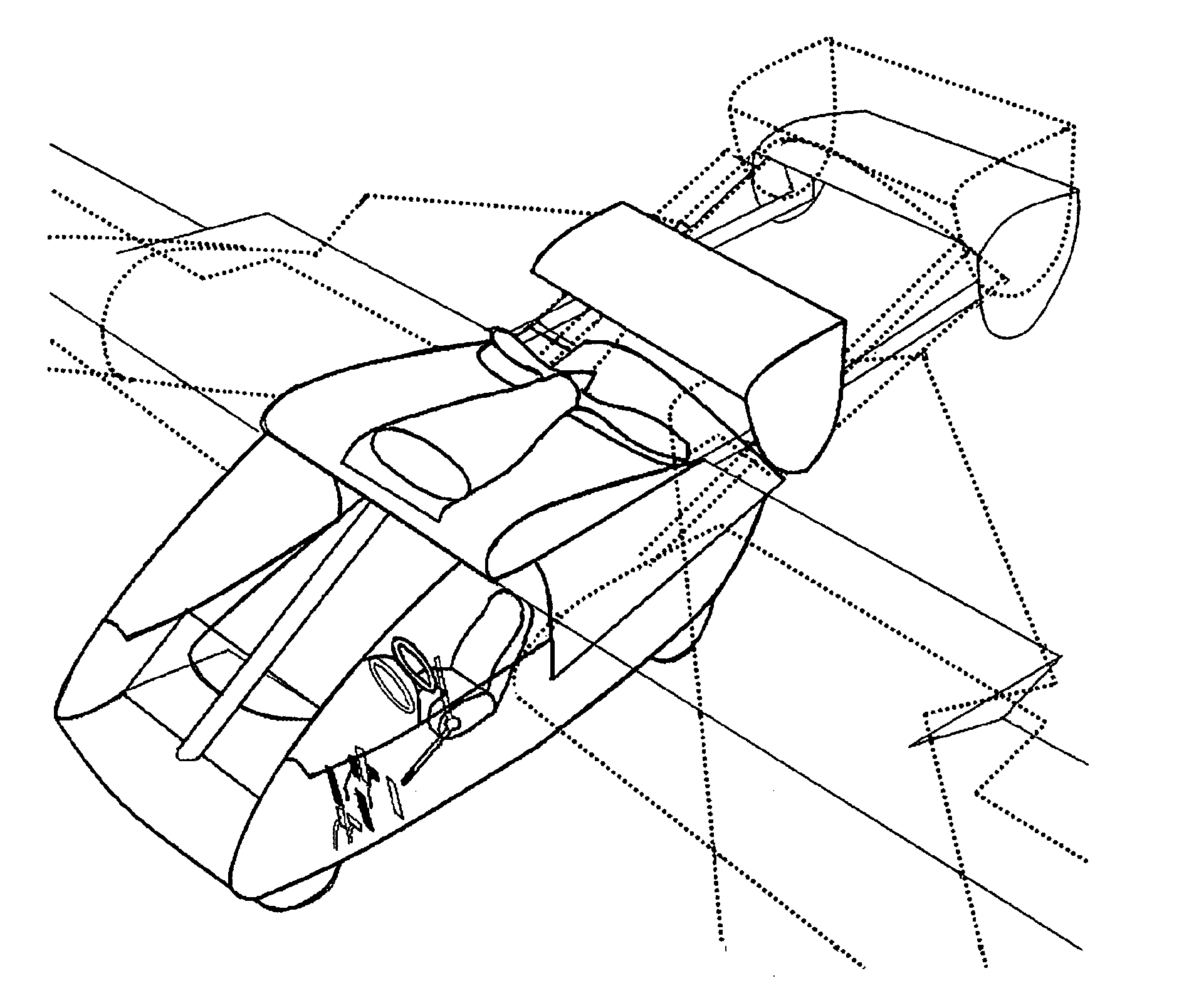
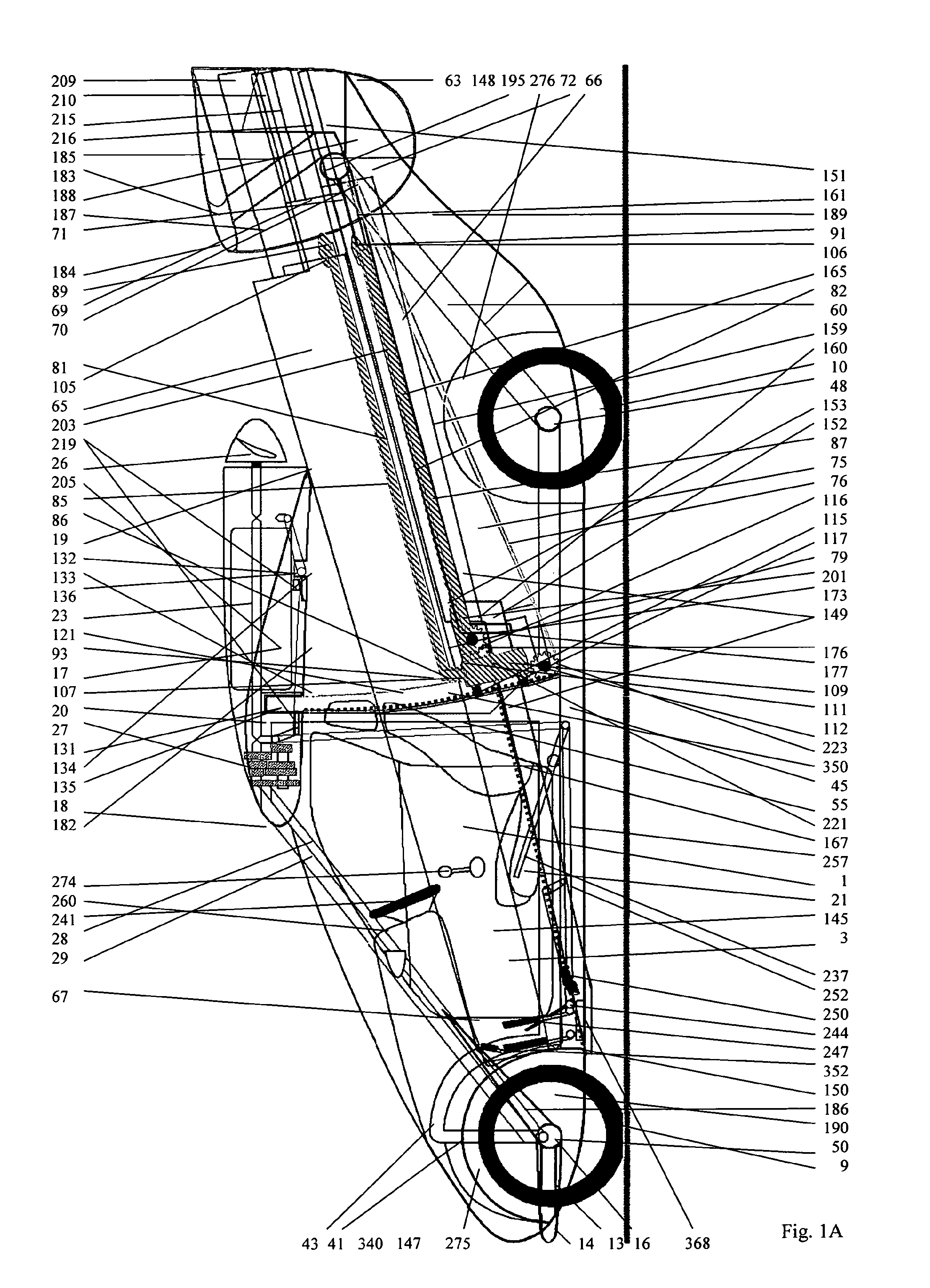
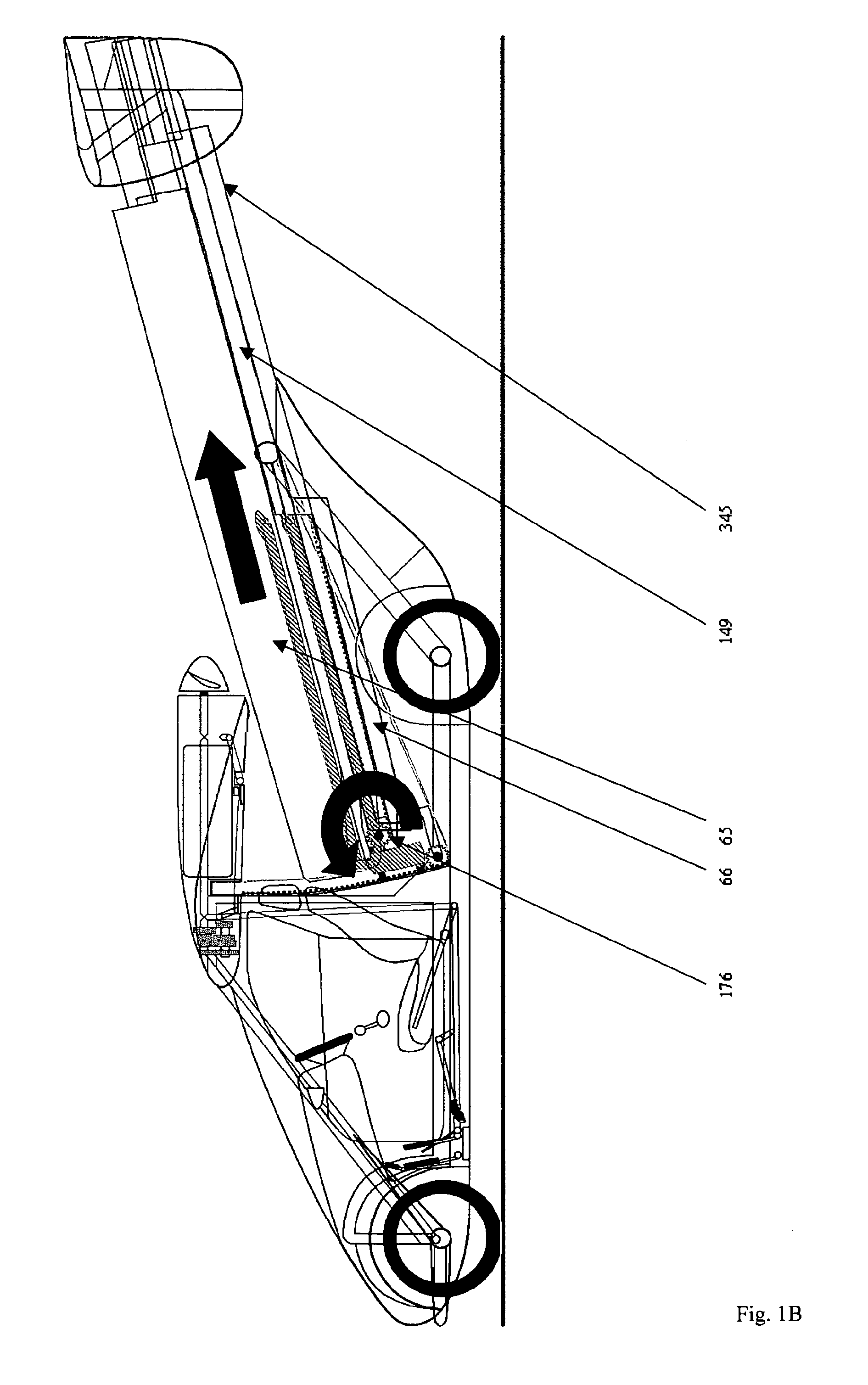
[0144]With reference to the attached drawings, the invention disclosed here in its preferred embodiment as a non-restrictive example is a vehicle comprising two separate “bodies”, “hulls” or fuselages 1,2. Each fuselage contains a cabin 145, 146 for one occupant (for a total of two occupants). Each cabin is accessible via a front-hinged door 3,4 located on the outer sides of the vehicle 337,338 (for a total of two doors).

[0145]The fuselages 1,2 are parallel to each other in line with the forward direction of movement 340. Underneath each fuselage 1,2 are two wheels (for a total of four wheels) 9,10,11,12. The wheels 9,10,11,12 are placed one behind the other along the underside of each fuselage. Only the lower part of each wheel emerges from the underside of the fuselage.

[0146]The fuselages 1,2 are connected to each other at two main points. At the lower front of the vehicle between the front w...


PUM


Abstract

Flying Car, readable aircraft, amphibian, multimode, multifunctional, composite versatile personal transport vehicle with twin, parallel fuselages, hulls, each with inflatable pontoons and/or wheels below and a cabin. Combined, aircraft, airplane, aeroplane, flying, air, aerial, airborne vehicle with variable, folding wings which is convertible via automatic transformation to a land vehicle and to a sea vessel. Two wings are stored between the fuselages. They extend on a system of rails, pivots and counter-rotating, fuselage-mounted arms which then sink flush into the wings' undersides and lock for flight. Upon wing extension and retraction, controls for road transport and flight controls alternately emerge or are stowed inoperably, as needed. Engine power alternately drives a propeller for flight, wheels for road travel and a separate, submersible, marine propeller for water transport.

Description

[0001]This invention integrates the features and functions of an automobile, winged light aircraft and motorboat into one vehicle. Its transformation from one configuration to another is automated. It has twin fuselages, a swing-wing mechanism and hybrid controls.BACKGROUND OF THE INVENTION[0002]Whereas almost all winged aircraft and most seaplanes have wheels and steering for taxiing on land, it is primarily their wingspan which makes them illegal or impractical for road transport. To be “roadable” the maximum allowed width varies between 2.44 m (8 ft.) and 2.55 m. In exceptions it ranges up to 2.60 m (8.5 ft.). Furthermore, cars are generally heavier, less streamlined and have a less critical centre of gravity than aircraft. Because of these major (and other minor) factors, a practical combined land / air vehicle (“flying car”) for everyday use has remained an unsolved technical problem for over 100 years.[0003]Some of the biggest names in the automobile industry have designed “flyi...

Claims


Application Information

Patent Timeline
Patent Type & Authority Applications(United States)
IPC IPC(8): B60F5/02B64C37/00
CPCB60F5/02B64C39/04B64C37/00
Inventor BROWN, JOHN
Owner FLECK FITNESS CONCEPTS
Why Eureka
Try Eureka