
Hydraulic valve system for actuating at least one shifting element of a transmission

Inactive Publication Date: 2013-05-23
ZF FRIEDRICHSHAFEN AG
View PDF17 Cites 3 Cited by
  • Summary
  • Abstract
  • Description
  • Claims
  • Application Information

AI Technical Summary

Benefits of technology

The valve device described in this patent has a more compact structure and is lighter than existing systems due to the arrangement of two valve slides. It can be made with the same number of connection points as separate control and switching valve devices. Additionally, using the integrated design simplifies duct configuration complexity and reduces costs compared to systems made with separate valves. The valve housing is made of lightweight aluminum. Overall, this valve device provides the same functions with a simplified and cost-effective design.

Problems solved by technology

Since the valve slide of the control valve device and the valve slide of the switching valve device are respectively arranged in separate valve bores, a hydraulic system, formed in such manner, takes up an undesirably large amount of space.

Method used


Image

  • Hydraulic valve system for actuating at least one shifting element of a transmission
  • Hydraulic valve system for actuating at least one shifting element of a transmission
  • Hydraulic valve system for actuating at least one shifting element of a transmission

Examples


Embodiment Construction

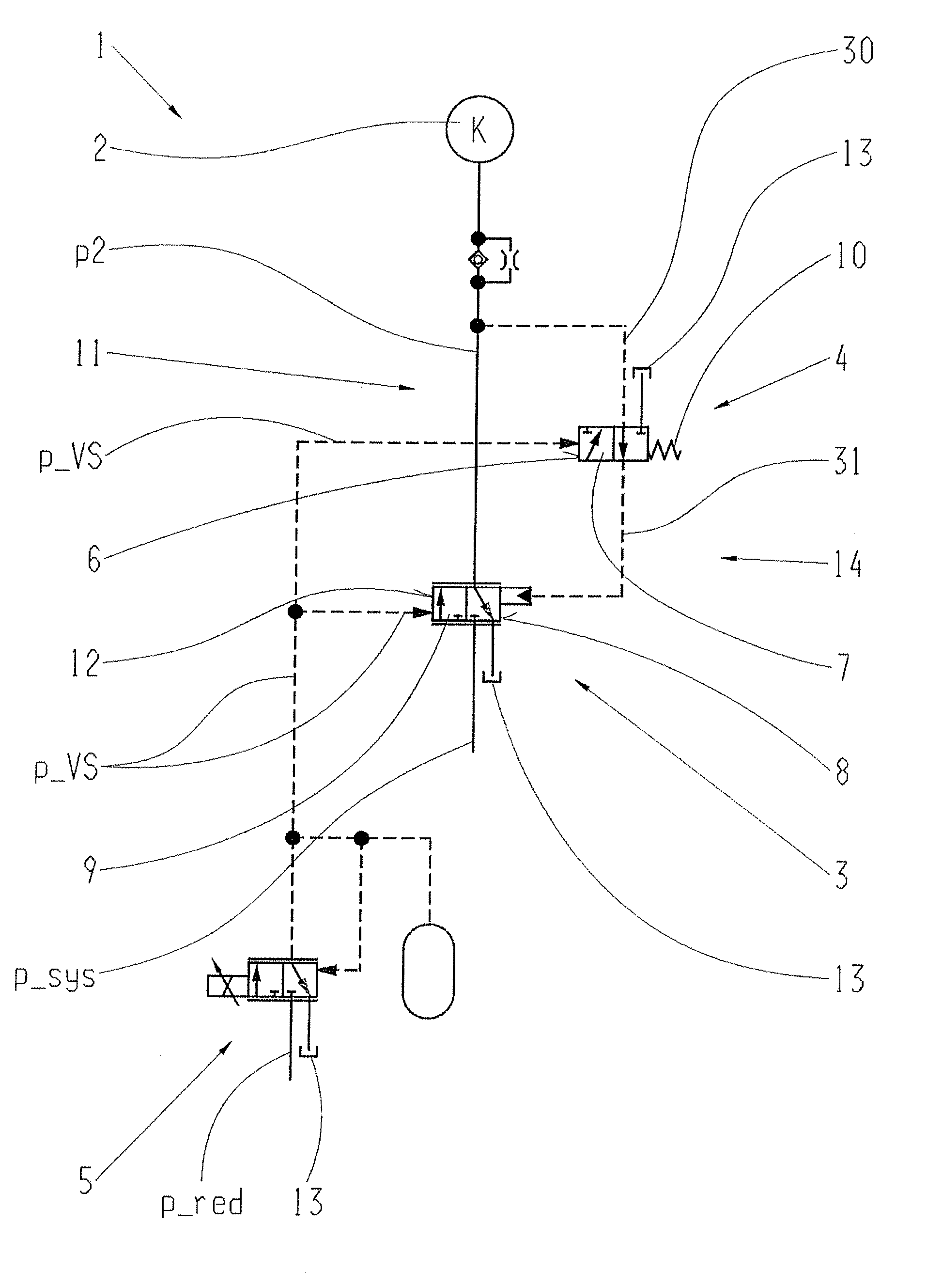
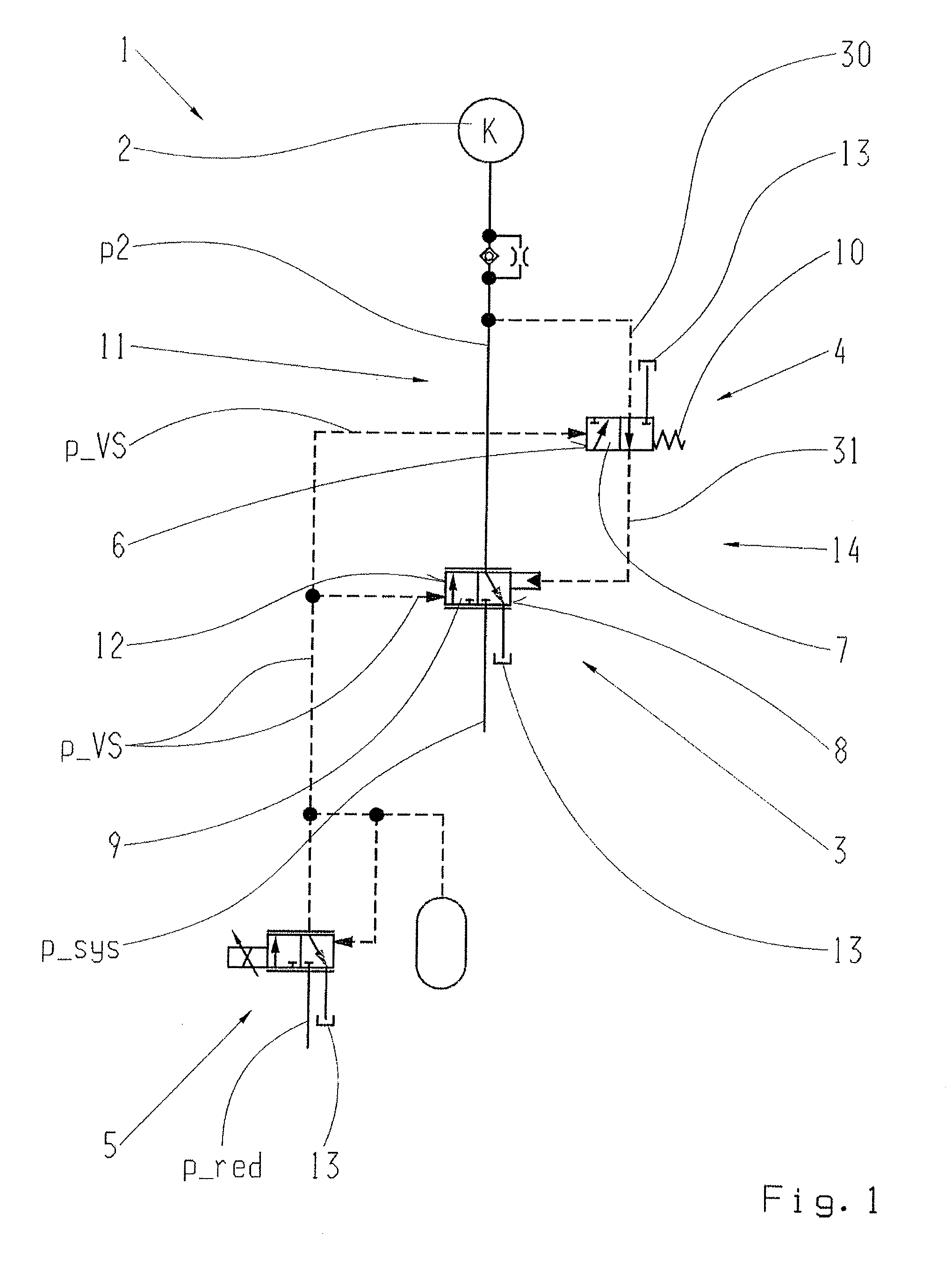
[0037]FIG. 1 shows part of a hydraulic system 1 for actuating a shifting element 2 of a transmission, wherein in the present case the shifting element 2 is a hydraulically actuated friction clutch of the transmission. As a function of a pressure or actuating pressure p2 that can be applied to the shifting element 2, the transmission capacity of the shifting element 2 can be varied between a value equal to zero and a maximum value.

[0038]The actuating pressure p2 of the shifting element 2 can be adjusted by means of a pilot-controlled control valve device 3 or clutch valve and functionally connected to it, an also pilot-controlled switching valve device 4 or holding valve. A pilot pressure p_VS that can be adjusted by means of an actuator can be applied both to the control valve 3 and to the switching valve 4. When the switching valve 4 is in a first switch condition the actuating pressure p2 of the shifting element 2 can be regulated by means of the control valve 3 within a defined p...


PUM


Abstract

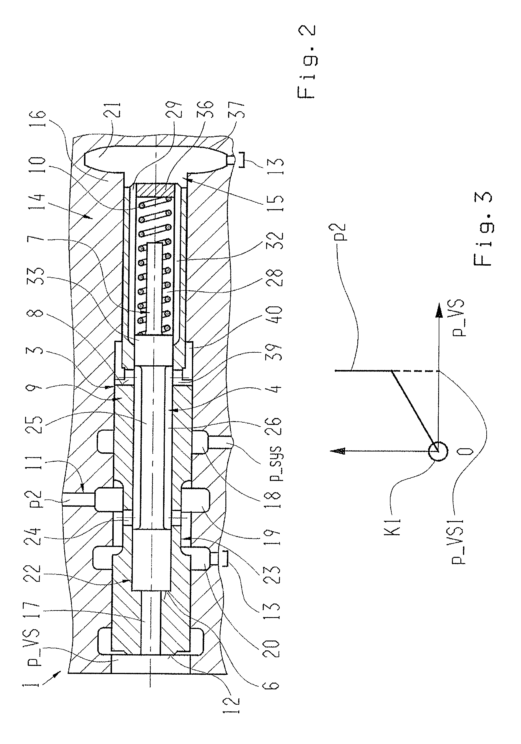
A valve device (14) of a hydraulic system (1) for actuating at least one shifting element (2) of a transmission. The valve device comprising a pilot-controlled control valve device (3) with a valve slide (9) and, functionally connected with this is, an also pilot-controlled switching valve device (4) which is also formed with a valve slide (7). The valve slides (7, 9) are arranged to move longitudinally in a common bore (15) of a valve housing (16) and are positioned coaxially with one another, and an inner valve slide (7) is arranged to move longitudinally at least partially within the outer valve slide (9).

Description

[0001]This application claims priority from German patent application serial no. 10 2011 086 655.8 filed Nov. 18, 2011.FIELD OF THE INVENTION[0002]The invention concerns a valve device of a hydraulic system for actuating at least one shifting element of a transmission.BACKGROUND OF THE INVENTION[0003]U.S. Pat. No. 7,282,005 B2 describes a hydraulic system for actuating a shifting element of a transmission, having a pilot-controlled control valve device comprising a valve slide and, functionally connected therewith, an also pilot-controlled switching valve device that is also made with a valve slide. By means of a pressure regulating device, the pilot pressure for the control valve device and the switching valve device is set as a function of an electric control signal, such that the pressure regulating device has a defined working pressure range which is usually substantially lower than the actuating pressure of the shifting element. To enable actuating the shifting element with hig...

Claims


Application Information

Patent Timeline
IPC IPC(8): F16H61/02F16K31/12F15B13/042
CPCF15B13/0403F16H2061/0279F16H61/0276F16K11/0716Y10T137/87193
Inventor HAUPT, JOSEF
Owner ZF FRIEDRICHSHAFEN AG
Learn More