Motor vehicle light, motor vehicle and method for operating a motor vehicle light

a technology for motor vehicles and light sources, applied in the direction of lighting and heating equipment, instruments, transportation and packaging, etc., can solve the problems of not being able to indicate a change in direction by means of moving lights, light-emitting diodes are not legal in all countries, and the driver is often unable to pay attention to all vehicles at the same time, so as to achieve a high-directional effect and facilitate the distribution of ligh

Inactive Publication Date: 2013-05-23
AUDI AG
View PDF0 Cites 48 Cited by
  • Summary
  • Abstract
  • Description
  • Claims
  • Application Information

AI Technical Summary

Benefits of technology

[0024]To avoid scattering losses in the light guide, the light should be deflected as seldom as possible. According to another advantageous feature of the present invention, the light source may have a main emission direction in which the light source emits light with maximum intensity. For example, light-emitting diodes may represent a light source with a particularly highly directional radiation pattern. The light source is then arranged in the motor vehicle light such that the main emission direction includes with the light exit face an angle in a range from 0° to 50°, in particular in a range from 0° to 30° with the light source, and thus radiates its light not into the direction in which the light exits from the light exit face of the motor vehicle light. Instead, the light source radiates transversely thereto, which makes it easier to distribute the light along the light exit face with the light guide.
[0025]The light guide may

Problems solved by technology

Especially in confusing traffic situations with many road users, a driver is frequently unable to pay attention to all vehicles simultaneously.
Another striking, but not always desirable characteristic

Method used


Image

  • Motor vehicle light, motor vehicle and method for operating a motor vehicle light
  • Motor vehicle light, motor vehicle and method for operating a motor vehicle light
  • Motor vehicle light, motor vehicle and method for operating a motor vehicle light

Examples


Embodiment Construction

[0034]Throughout all the figures, same or corresponding elements may generally be indicated by same reference numerals. These depicted embodiments are to be understood as illustrative of the invention and not as limiting in any way. It should also be understood that the figures are not necessarily to scale and that the embodiments are sometimes illustrated by graphic symbols, phantom lines, diagrammatic representations and fragmentary views. In certain instances, details which are not necessary for an understanding of the present invention or which render other details difficult to perceive may have been omitted.

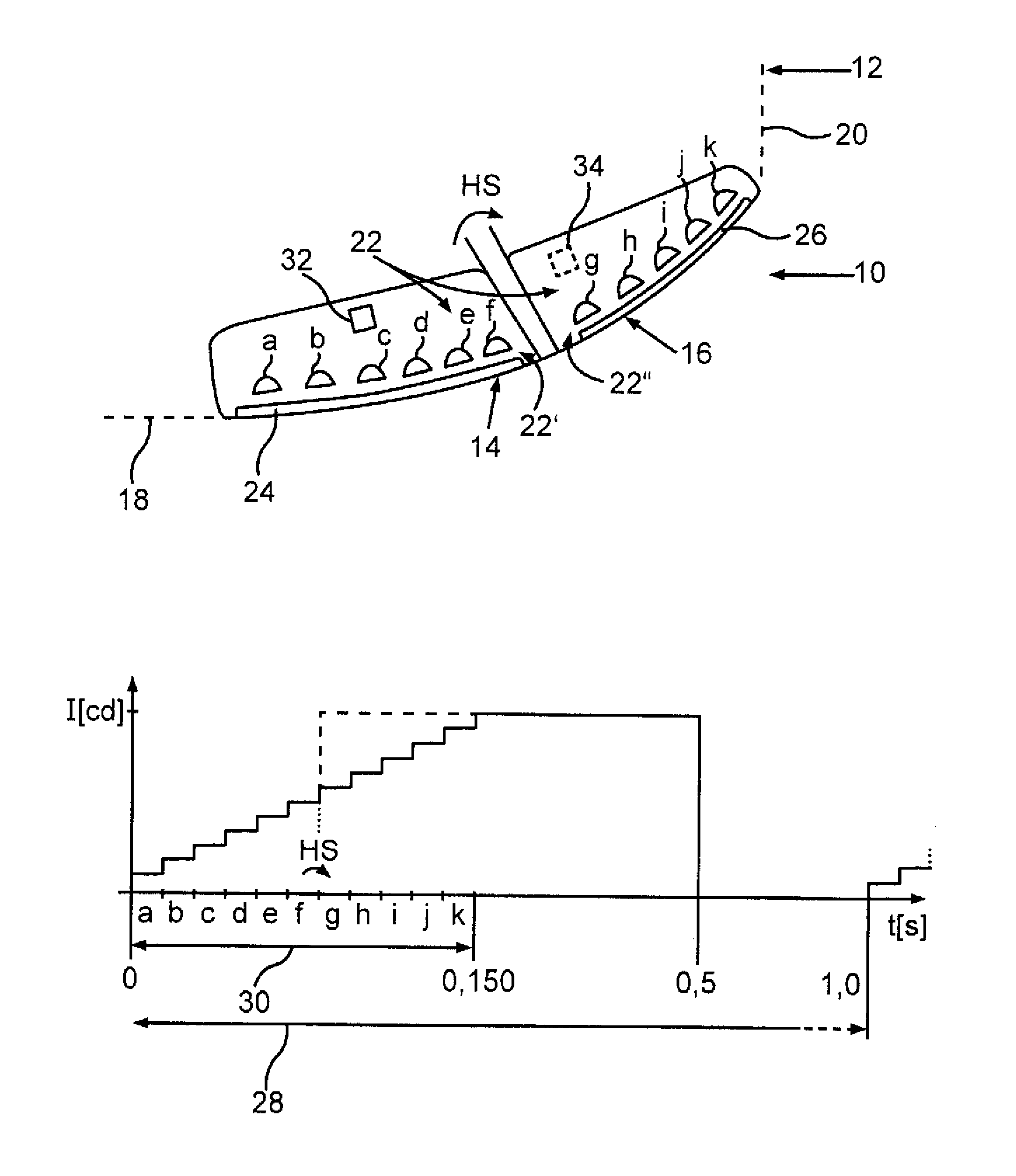
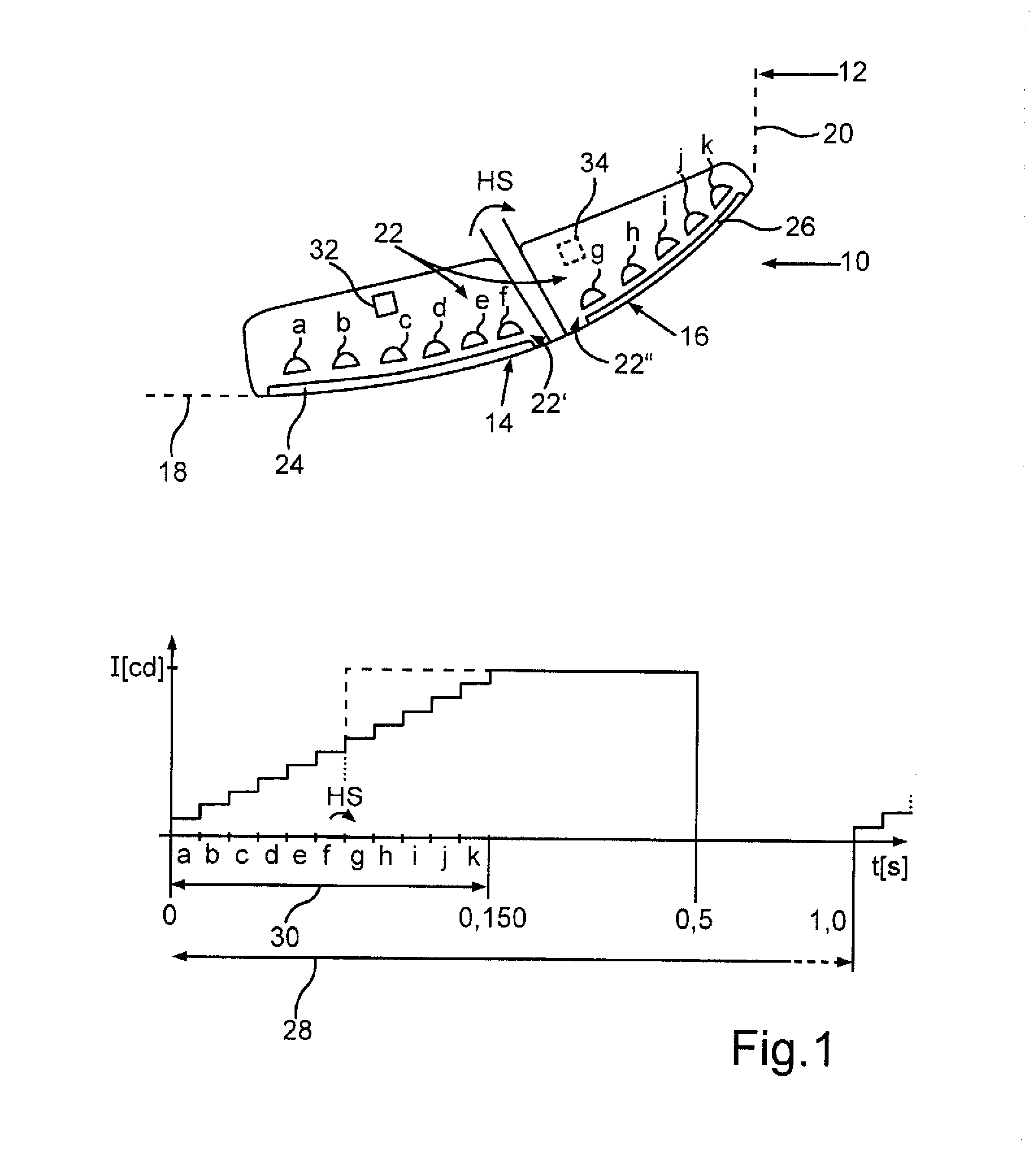
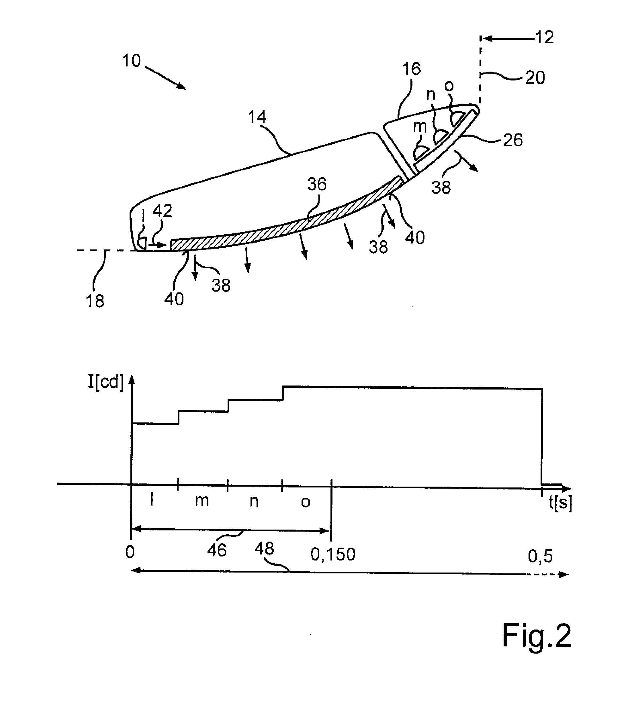
[0035]Turning now to the drawing, and in particular to FIG. 1, there is shown a motor vehicle light 10 installed, for example, in a road vehicle 12, for example in a passenger car. The motor vehicle light 10 may be, for example, a front headlamps with integrated turn signal and daytime running light or a tail light with integrated brake light, tail light and turn signal. The...


PUM


Abstract

A motor vehicle light providing easily identifiable and interpretable signals for other road users includes in its interior a light guide which is configured to receive at least a part of a light from a light source, distributes the received light along a light exit face and scatters the distributed light toward the light exit face. The light source is composed of light-emitting diodes which are switched on sequentially and/or which are first supplied with different electrical power levels, whereafter their brightness is matched by controlling the power levels. When the motor vehicle light is switched on, the increase in brightness then appears to be continuous to an observer.

Description

CROSS-REFERENCES TO RELATED APPLICATIONS[0001]This application claims the priority of German Patent Application, Serial No. 10 2011 119 231.3, filed Nov. 23, 2011, pursuant to 35 U.S.C. 119(a)-(d), the content of which is incorporated herein by reference in its entirety as if fully set forth herein.BACKGROUND OF THE INVENTION[0002]The present invention relates to a motor vehicle light for a motor vehicle, in which light can be generated by a light source and emitted to the outside by passing through a light exit face. The invention also relates to a method for operating a motor vehicle light and a motor vehicle with a motor vehicle light.[0003]The following discussion of related art is provided to assist the reader in understanding the advantages of the invention, and is not to be construed as an admission that this related art is prior art to this invention.[0004]It is desirable in the interests of road safety that motor vehicles, i.e. road vehicles such as cars or trucks, alert ot...

Claims


Application Information

Patent Timeline
IPC IPC(8): B60Q1/02F21V13/02F21V8/00F21W107/10
CPCB60Q1/0041B60Q1/382B60Q1/34B60Q1/304B60Q1/381
Inventor HUHN, WOLFGANGSTADTLER, MANFREDFREUDENBERGER, MONA
Owner AUDI AG
Why Eureka
Try Eureka