Backlight module and assembling method thereof

a backlight module and backlight technology, applied in the field of backlight modules, can solve the problems of adversely affecting the optical performance and assembly of quantum dot displays, and achieve the effect of enhancing mounting strength

Active Publication Date: 2013-05-23
AU OPTRONICS CORP
View PDF5 Cites 21 Cited by
  • Summary
  • Abstract
  • Description
  • Claims
  • Application Information

AI Technical Summary

Benefits of technology

[0009]In order to solve the problems of the prior art, the invention provides an improved backlight module, in which a light emitter includes a particularly designed clamping arm formed on a base thereof. The clamping arm of the base can be used to clamp a wavelength converter, so the light emitter and the wavelength converter can be mounted to each other without the use of an adhesive (e.g., a LOCA) to thereby solve the problem of overflowing of the adhesive. In addition, when the wavelength converter is adhered to a side of a light guide plate of the backlight module by using a LOCA, the LOCA also adheres to the clamping arm that clamps the wavelength converter, so as to enhance the mounting strength between the wavelength converter and the light guide plate. Furthermore, engaging structures are respectively disposed on the clamping arm of the base and the light guide plate, so the LOCA between the wavelength converter and the light guide plate can be blocked by the clamping arm when the base of the light emitter abuts against the light guide plate, so as to prevent the LOCA from overflowing onto the upper surface and the lower surface of the light guide plate.

Problems solved by technology

Because the LOCA is a liquid and therefore has a certain degree of fluidity, overflowing of the LOCA may occur to thereby adversely affect the optical performance and assembly of the quantum dot display.

Method used


Image

  • Backlight module and assembling method thereof
  • Backlight module and assembling method thereof
  • Backlight module and assembling method thereof

Examples


Embodiment Construction

[0031]Reference will now be made in detail to the present embodiments of the invention, examples of which are illustrated in the accompanying drawings. Wherever possible, the same reference numbers are used in the drawings and the description to refer to the same or like parts.

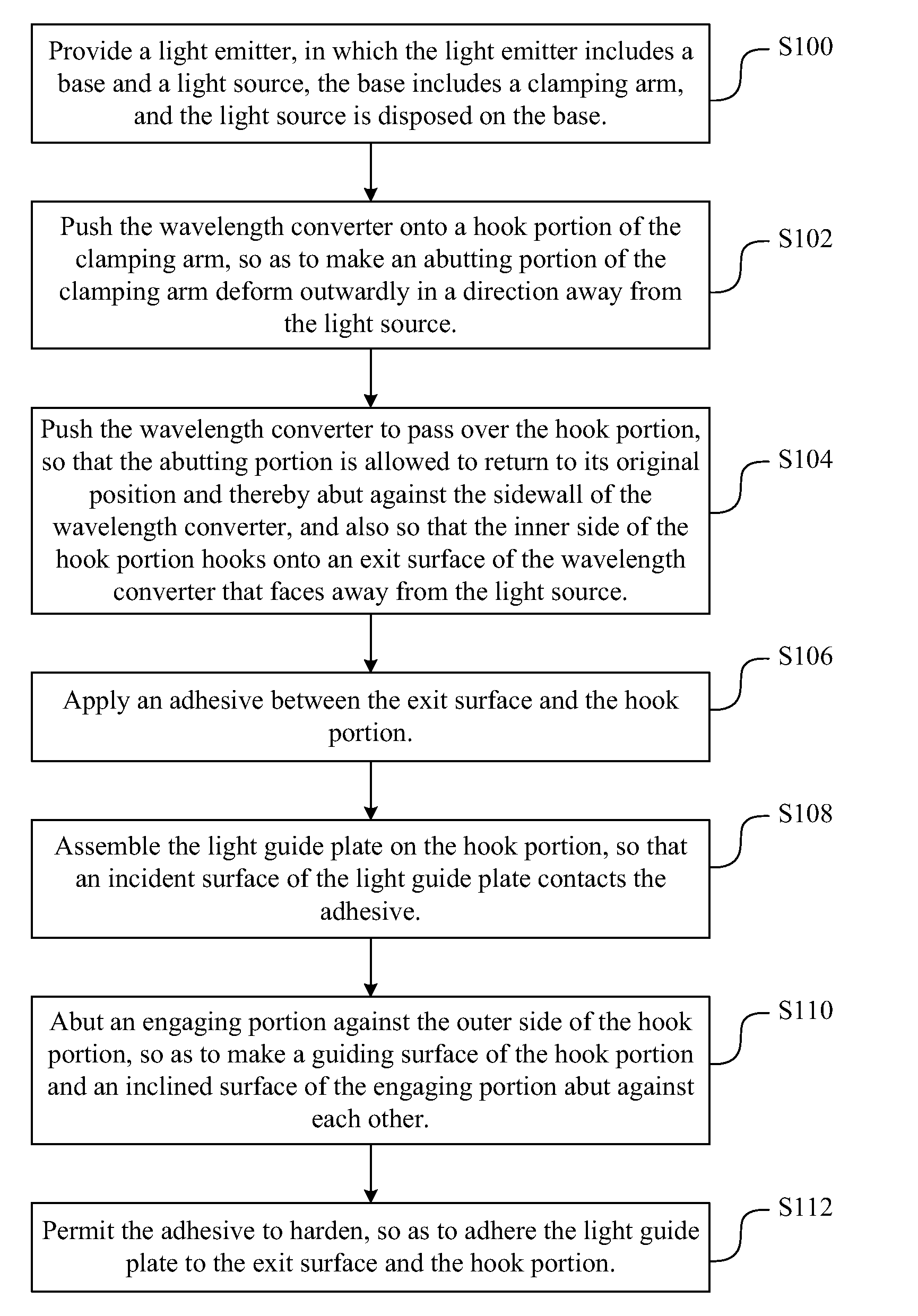
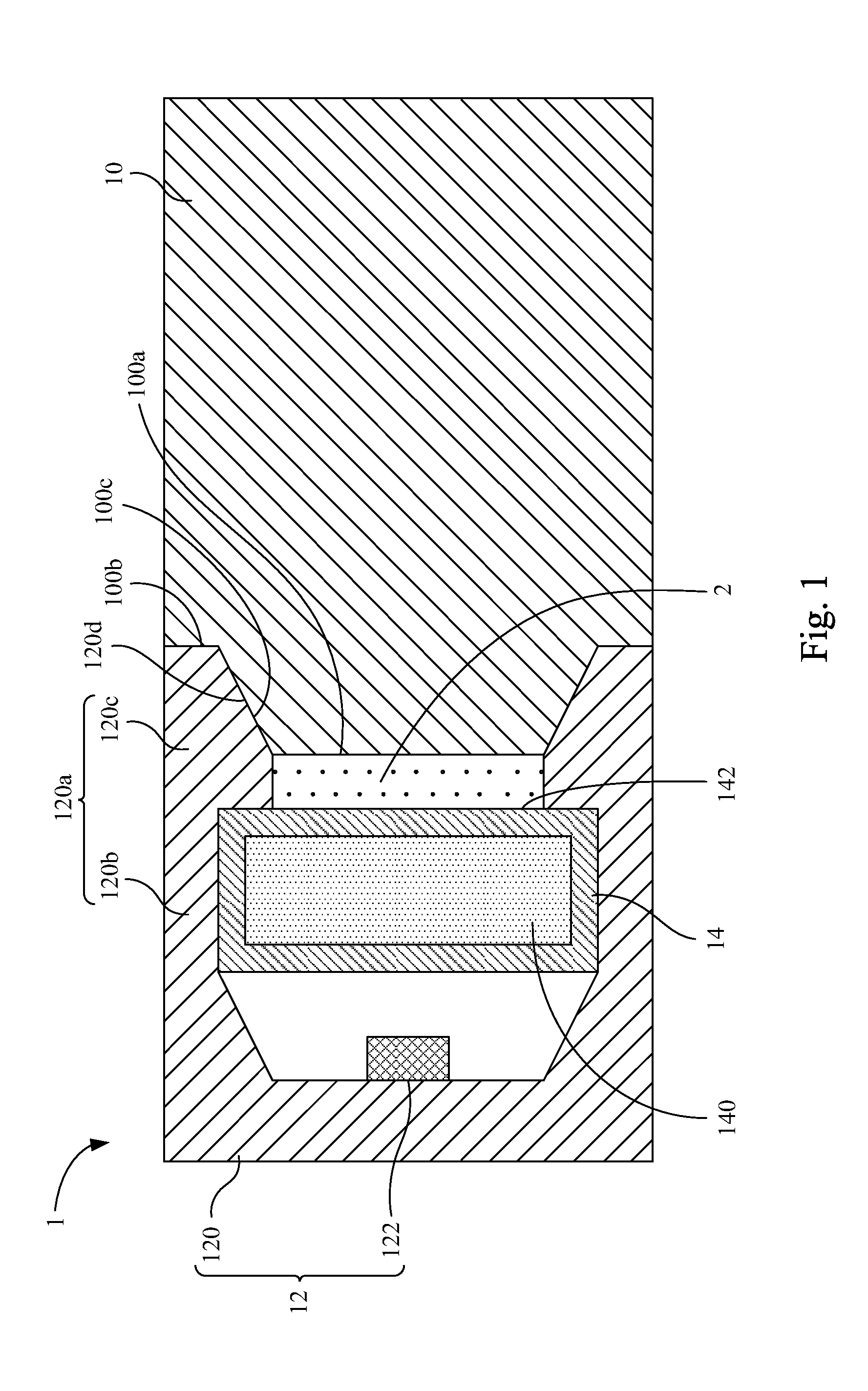
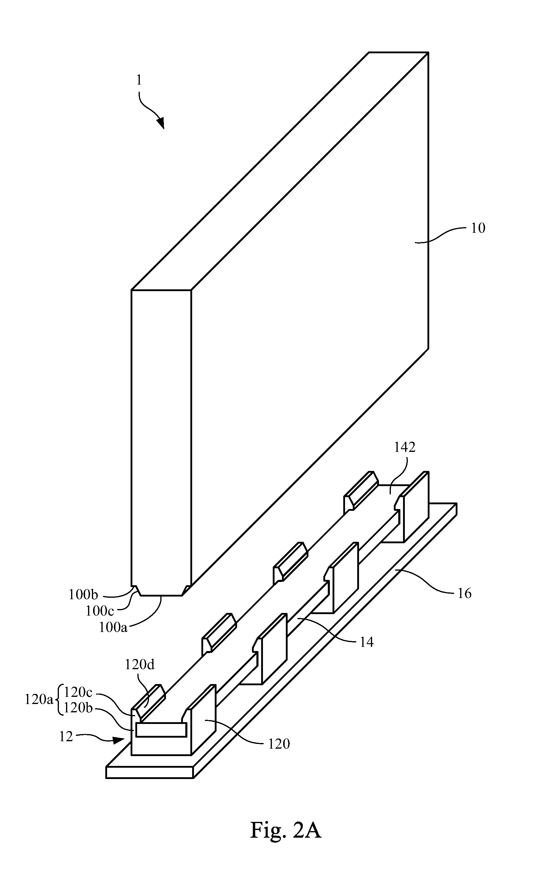
[0032]An improved backlight module is provided. Specifically, a light emitter of the backlight module includes a particularly designed clamping arm formed on a base thereof. The clamping arm of the base can be used to clamp a wavelength converter, so the light emitter and the wavelength converter can be mounted to each other without the use of an adhesive (e.g., a LOCA) to thereby solve the problem of overflowing of the adhesive. In addition, when the wavelength converter is adhered to a side of a light guide plate of the backlight module by using a LOCA, the LOCA also adheres to the clamping arm that clamps the wavelength converter, so as to enhance the mounting strength between the wavelength converter and t...


PUM

PropertyMeasurementUnit
wavelength convertingaaaaaaaaaa
wavelengthaaaaaaaaaa
sizeaaaaaaaaaa

Abstract

A backlight module includes a light guide plate, at least one light emitter, and a wavelength converter. The light guide plate has an incident surface. The light emitter is disposed at a side of the light guide plate and corresponds in position to the incident surface. The light emitter includes a base and a light source. The base includes a clamping arm. The clamping arm substantially extends toward the light guide plate. The light source is disposed on the base. The wavelength converter is located between the light guide plate and the light source and is clamped by the clamping arm.

Description

RELATED APPLICATIONS[0001]This application claims priority to Taiwan Application Serial Number 100142060, filed Nov. 17, 2011, which is herein incorporated by reference.BACKGROUND[0002]1. Field of Invention[0003]The present invention relates to a backlight module.[0004]2. Description of Related Art[0005]In recent years, owing to the rapid development of the electronics and information industries, products developed by these industries are becoming increasingly sophisticated. For current personal computers, in addition to efforts to realize faster and more powerful computing units and to offer a wide range of peripheral equipment to meet user needs, a key area of development in the computer industry relates to realizing a more compact size, lighter weight, and thinner profile for personal computers.[0006]Liquid crystal displays have the advantages of high definition, small size, lightweight, low driving voltage, and low power consumption. Moreover, liquid crystal displays can be used...

Claims


Application Information

Patent Timeline
Patent Type & Authority Applications(United States)
IPC IPC(8): F21V8/00B23P11/00
CPCF21S8/00F21V13/02F21V17/10Y10T29/49826G02B6/0068G02B6/0091G02B6/0023
Inventor LEE, KENG-YI
Owner AU OPTRONICS CORP
Why Eureka
Try Eureka