
Outboard motor

a technology for outboard motors and motors, applied in the direction of propulsive elements, marine propulsion, vessel construction, etc., can solve the problems of large outboard motors, damage to gear mechanisms, complex structure,

Inactive Publication Date: 2013-05-23
HONDA MOTOR CO LTD
View PDF4 Cites 4 Cited by
  • Summary
  • Abstract
  • Description
  • Claims
  • Application Information

AI Technical Summary

Benefits of technology

The invention aims to solve the problem of wear debris damaging gear mechanisms in outboard motors. The invention provides a way to detect the amount of wear debris without making the structure more complex or larger. This prevents the gear mechanism from being damaged by the wear debris.

Problems solved by technology

In the case where such wear debris is generated, it may be caught in the gear mechanism as obstacles and it possibly damages the gear mechanism, disadvantageously.
However, when it is configured to provide the branch passage and detecting section as taught in the reference, it causes a larger outboard motor and complex structure, disadvantageously.

Method used


Image

  • Outboard  motor
  • Outboard  motor
  • Outboard  motor

Examples


Embodiment Construction

[0018]An outboard motor according to an embodiment of the present invention will now be explained with reference to the attached drawings.

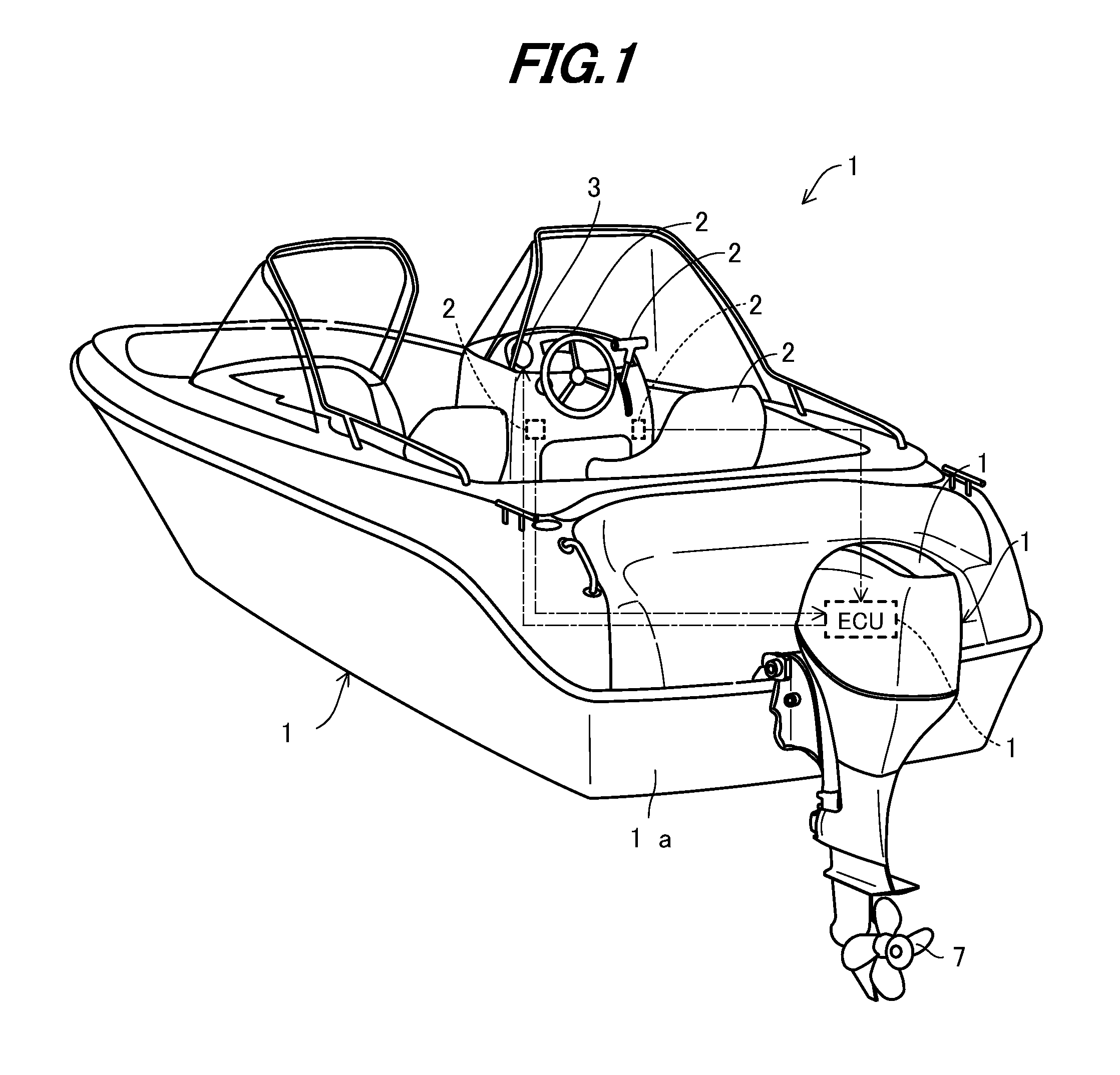
[0019]FIG. 1 is an overall schematic view of an outboard motor including a boat (hull) according to an embodiment of the invention.

[0020]In FIG. 1, symbol 1 indicates the boat or vessel whose hull 12 is mounted with the outboard motor 10. As illustrated, the outboard motor 10 is clamped (fastened) to the stern or transom 12a of the hull 12.

[0021]The outboard motor 10 has an internal combustion engine (prime mover; not shown in FIG. 1) and an engine cover 14 that covers the engine. The engine cover 14 is installed in its interior space (which is an engine room) with an Electronic Control Unit (ECU) 16 in addition to the engine. The ECU 16 has a microcomputer including a CPU, ROM, RAM and other devices and controls the operation of the outboard motor 10.

[0022]A steering wheel 22 is installed near a cockpit (operator's seat) 20 of the hull 12 to be r...


PUM


Abstract

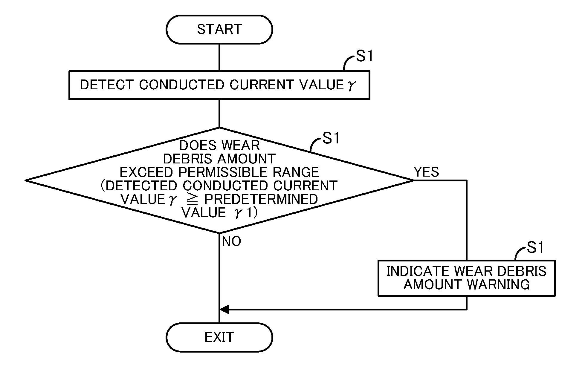
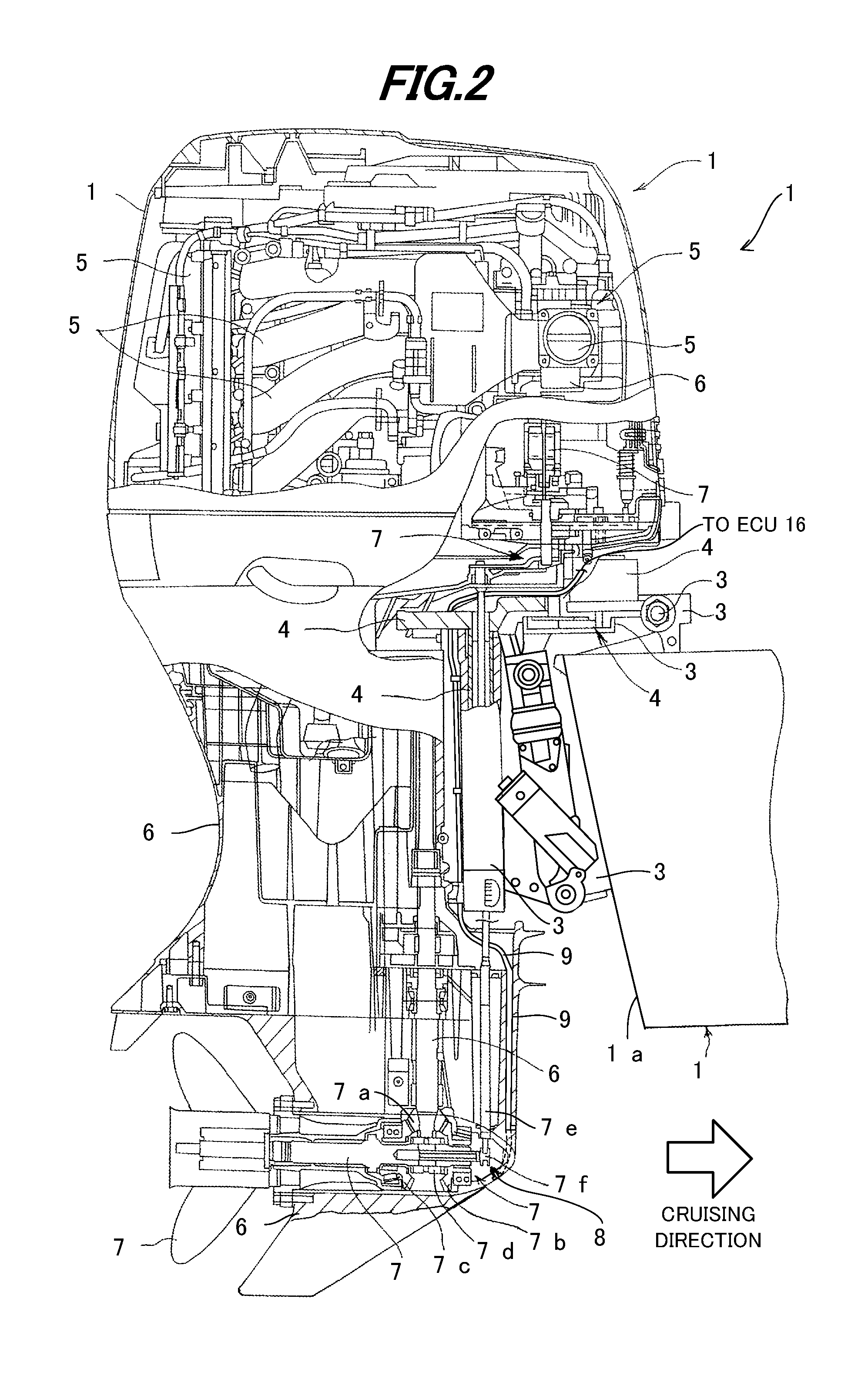
In an outboard motor having a prime mover, a gear mechanism transmitting a driving force of the prime mover to a propeller, and a gear case housing the gear mechanism, it is configured to have a drain bolt fastened to a drain hole bored at the gear case and constituted as a magnetic member; a stacked portion provided at an exposed part of the drain bolt in an inside of the gear case and having a conductor, an insulator and a resistive element partially making contact with the conductor that are stacked in a gravitational direction; a current detector detecting a current value conducted from the conductor to the drain bolt under a condition where voltage is applied to the conductor; and a wear debris amount detector adapted to detect an amount of wear debris of the gear mechanism deposited at the drain bolt based on the conducted current value.

Description

BACKGROUND[0001]1. Technical Field[0002]An embodiment of the invention relates to an outboard motor, particularly to an outboard motor that can detect wear debris of a gear mechanism.[0003]2. Background Art[0004]Conventionally, there is widely known an outboard motor in which a driving force of a prime mover such as an internal combustion engine is transmitted to a propeller through a gear mechanism. When the driving force is transmitted, gears of the gear mechanism are rubbed against each other so that they are worn, sometimes resulting in wear debris (i.e., metal powder, etc.). In the case where such wear debris is generated, it may be caught in the gear mechanism as obstacles and it possibly damages the gear mechanism, disadvantageously.[0005]To cope with it, in Japanese Laid-Open Patent Application No. Hei 6 (1994)-33730 (730), a branch passage used to circulate oil (lubricating oil) is connected to a gear case housing the gear mechanism and the branch passage is installed with ...

Claims


Application Information

Patent Timeline
Patent Type & Authority Applications(United States)
IPC IPC(8): B63H20/00B63H21/38
CPCB63H20/00
Inventor KURIYAGAWA, KOJISHIMIZU, NORIKAZUIKEDA, HIKARU
Owner HONDA MOTOR CO LTD
Learn More