Diagnostic system

a diagnostic system and integrated technology, applied in the field of integrated systems for diagnostics in humans and animals, can solve the problems of multiple devices, complicated instructions for testing or diagnosing,

Inactive Publication Date: 2013-05-23
ATOMO DIAGNOSTICS PTY LTD
View PDF7 Cites 4 Cited by
  • Summary
  • Abstract
  • Description
  • Claims
  • Application Information

AI Technical Summary

Benefits of technology

[0023]In one form the opening is positioned such that the test material can interface with the diagnostic equipment through the opening.

Problems solved by technology

However, personally performing these relatively immediate tests, assays or diagnoses can require complicated instruction and multiple devices.

Method used


Image

  • Diagnostic system
  • Diagnostic system
  • Diagnostic system

Examples


second embodiment

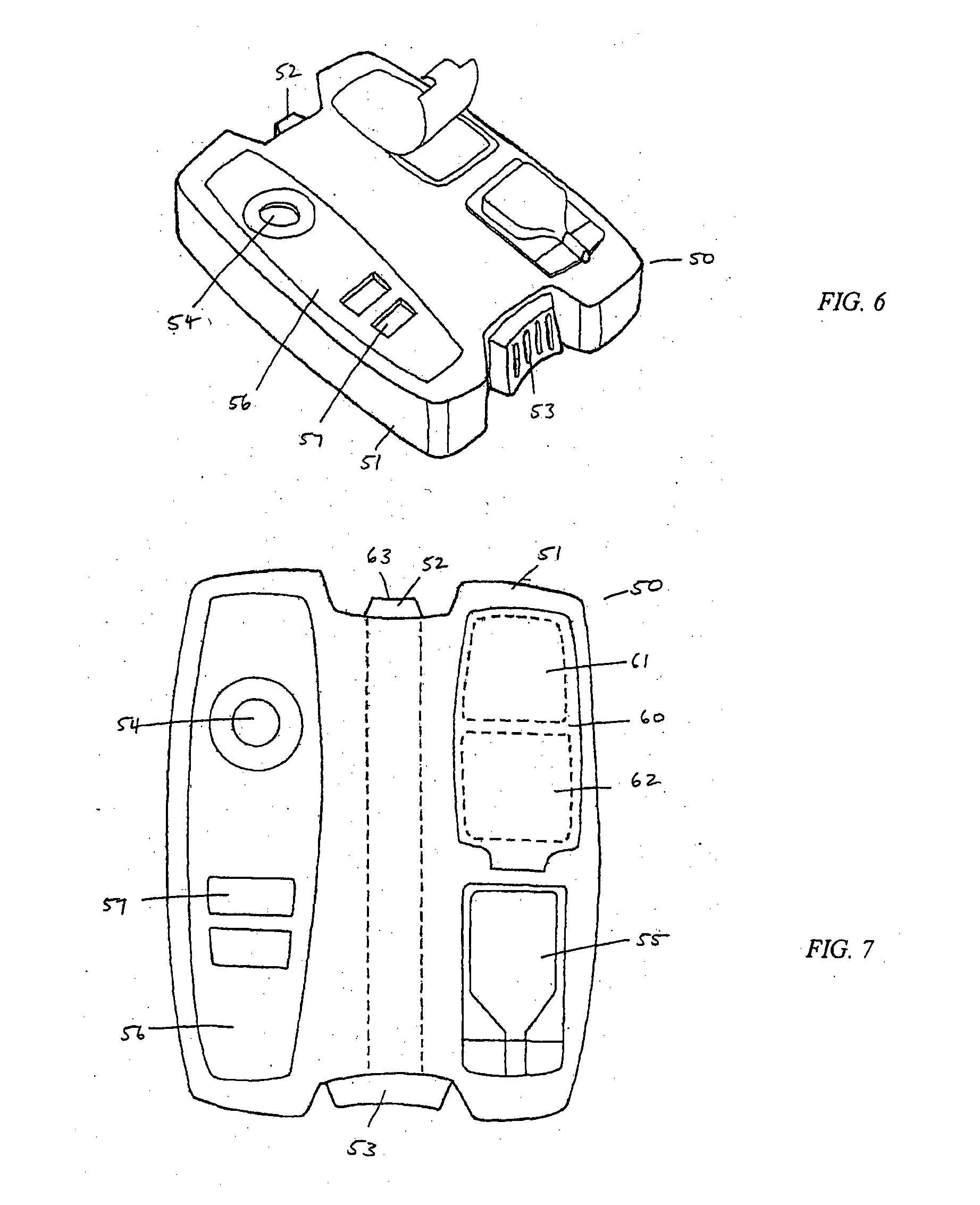
[0064]In the present diagnostic system, shown in FIGS. 6-7, the diagnostic system (50) comprises a body (51) in the form of a substantially H-shaped housing.

[0065]In the illustrated form, the housing includes an integrated lancet (52) which extends substantially through the housing (51). The lancet (52) is moveable between a rest position in which the lancet tip is enclosed within the body (51) and an actuated position in which the lancet tip extends from the body (51). The lancet (52) is actuated by a lancet activator (53) positioned at one end of the body (51).

[0066]While the illustrated forth includes a membrane penetration element in the form of a lancet, persons skilled in the art will be aware that the, membrane penetration element could be any piercing, slicing, cutting, puncturing or pricking element which allows a user to penetrate a membrane such as the skin to allow a fluid sample to be released.

[0067]The diagnostic system further comprises a blood collection window (54) ...

third embodiment

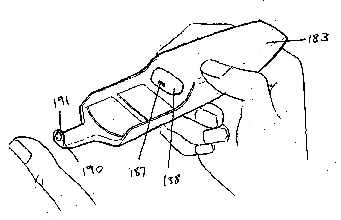
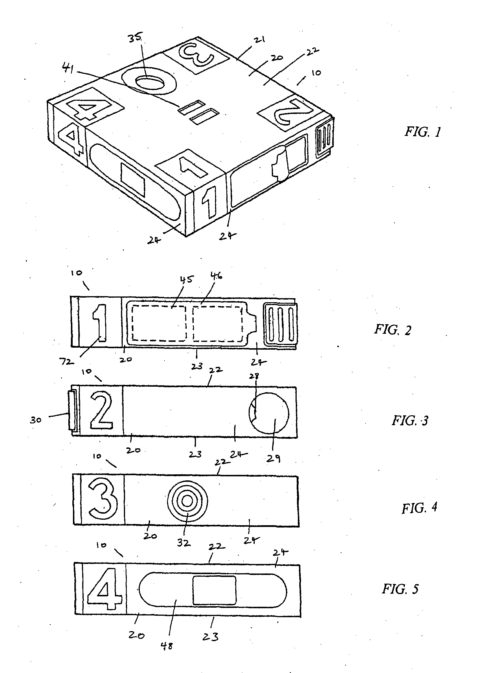
[0071]In a third embodiment a diagnostic system (70) comprises a body (71) in the form of a housing having six sides. The sides are labelled with indicia (72) indicating the order of which the sides are, to be used. A user will initially peel foil (73) from over an alcohol swab and dry wipe (74 and 75) which are positioned within an alcohol swab locator in the form of a depression (76) in one side of the diagnostic system (70). The user will clean their finger with the alcohol swab and then will insert their finger into finger pad depression (78) on a second side of the diagnostic system (70). An integrated lancet (79) is positioned within this side and actuated by lancet activator (80). Once the user has contacted lancet activator (80) the lancet tip extends from the body (71) to pierce a finger in the aperture (78). The lancet tip then retracts. The user then allows their blood to be collected at blood collection window (82) on a third side of the diagnostic system (70).

[0072]A so...

fourth embodiment

[0074]A fourth embodiment is shown in FIGS. 13-15. In this embodiment a diagnostic system (100) comprises a body (101) in the form of an elongate housing. The body (101) includes a finger pad aperture (102) which is positioned adjacent a lancet (103). The lancet (103) is integrated into the body (101) and is moveable between a position in which the lancet tip is enclosed within the body (101) and a position in which the lancet tip extends from the body into the finger pad aperture (102).

[0075]The diagnostic system further comprises a lancet activator (104) which is actuated to move the lancet between the rest position in which it is enclosed in the body (101) and the actuator position in which it extends into the finger pad depression point (102). The reverse side of the body (101) comprises a solution delivery actuator in the form of a push button (106), along with a blood collection window (107) and results window (108). In use, a user inserts their finger into the finger pad aper...


PUM


Abstract

A composite diagnostic system comprising a support member having a membrane penetration element; a bodily fluid collection point positioned for collection of a bodily fluid released by application of the membrane penetration element to a user's body; a test material positioned in the support member such that in use the bodily fluid is brought into contact with the test material.

Description

TECHNICAL FIELD[0001]The present disclosure broadly relates to an integrated system for diagnostics in humans and animals.BACKGROUND OF THE DISCLOSURE[0002]Systems for performing relatively immediate tests, assays or diagnoses with relative ease are known. However, personally performing these relatively immediate tests, assays or diagnoses can require complicated instruction and multiple devices.SUMMARY OF THE DISCLOSURE[0003]Disclosed is a composite diagnostic system comprising a support member, the support member having a membrane penetration element; a bodily fluid collection element positioned for collection of a bodily fluid released by application of the membrane penetration element to a user's body; and a test material positioned in the support member such that in use the bodily fluid is brought into contact with the test material.[0004]In one form the test material comprises a test strip positioned in the composite diagnostic system. In one form the test material comprises a...

Claims


Application Information

Patent Timeline
Patent Type & Authority Applications(United States)
IPC IPC(8): A61B5/157A61B5/15A61B5/145A61B5/151
CPCA61B5/1411A61B5/14532A61B5/15186A61B5/157A61B2562/0295B01L3/502A61B5/150343A61B5/150358A61B5/151A61B5/15192A61B5/145A61B5/150022A61B5/150305A61B5/150412A61B5/150503A61B5/150549A61B5/150618A61B5/150717A61B5/150755A61B5/150824A61B5/15111A61B5/15113A61B5/15117A61B5/15144A61J1/05B01L3/5023B01L2200/0605B01L2200/16B01L2300/14B01L2400/0475
Inventor KELLY, JOHN MICHAELSIU, ERICNORCOTT, ALISON RUTHDUNN, CHRISTOPHER DAVIDJOHNSON, IAN FREDERICKHUESO, ERNESTO MONISSOKOLOV, RICHARD
Owner ATOMO DIAGNOSTICS PTY LTD
Why Eureka
Try Eureka