Electric motor and electric unit including the same

a technology of electric motors and electric motors, applied in the direction of machines/engines, positive displacement liquid engines, pumping machines, etc., can solve the problems of motor shaft whirling, vibration or abnormal noise, etc., to suppress the generation of abnormal noise of electric motors and facilitate the centering of rotors.

Inactive Publication Date: 2013-05-30
JTEKT CORP
View PDF11 Cites 7 Cited by
  • Summary
  • Abstract
  • Description
  • Claims
  • Application Information

AI Technical Summary

Benefits of technology

[0010]It is possible to easily perform centering of a rotor supported by bearings arranged at two positions, via the holding member, and to perform centering of the stator via the fixing member, using the outer diameters of the rotor and the stator as references. As a result, it is possible to suppress generation of vibrations and abnormal noise of the electric motor. Furthermore, stepped portions, extending in the circumferential direction, are formed respectively in an axial end portion of the outer periphery of the holding member and an axial end portion of the inner periphery of the fixing member, and are brought into contact with each other. Therefore, when the housing of the rotated member and the holding member are fastened with the bolts, the stator is pushed toward the housing of the rotated member via the fixing member by the fastening force of the bolts. Therefore, it is possible to perform centering of the stator and centering of the rotor at the same time, thereby reliably fixing the electric motor and the housing of the rotated member.

Problems solved by technology

In an electric motor used in the electric oil pump device or in an electric power steering system, whirling of a motor shaft may become large due to, for example, runout, backlash or eccentricity between a stator and a rotor of the electric motor, or an attraction force generated by unbalance between the stator and the rotor and therefore vibrations or abnormal noise of the electric motor may be generated.

Method used


Image

  • Electric motor and electric unit including the same
  • Electric motor and electric unit including the same
  • Electric motor and electric unit including the same

Examples


Embodiment Construction

[0015]Hereinafter, embodiments of the invention will be described with reference to the accompanying drawings.

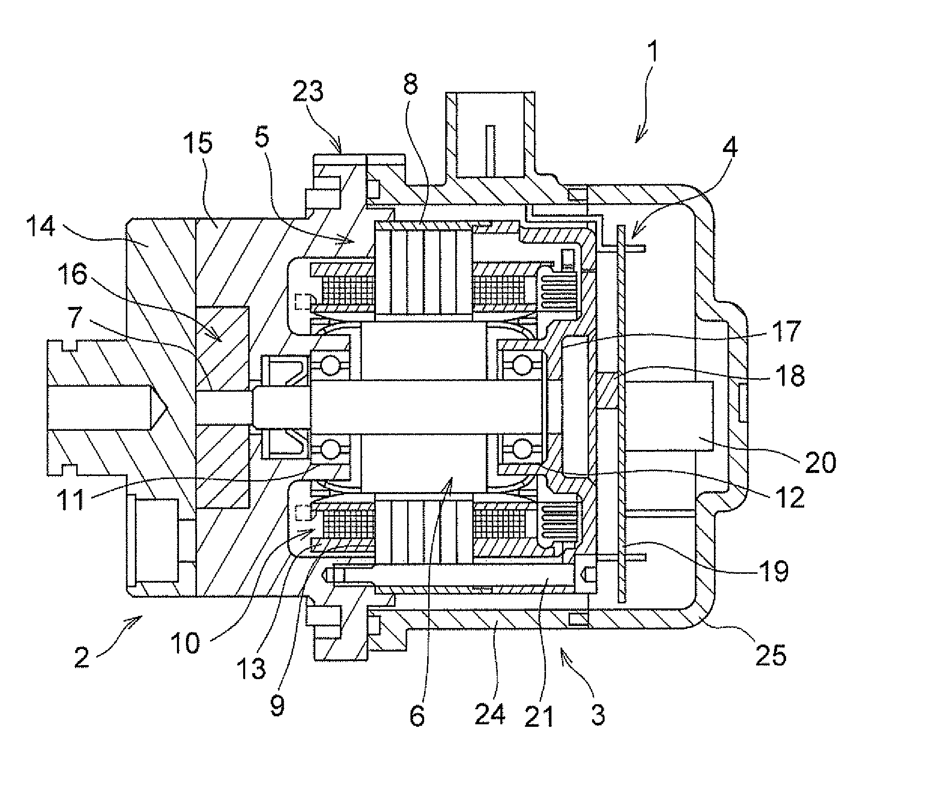
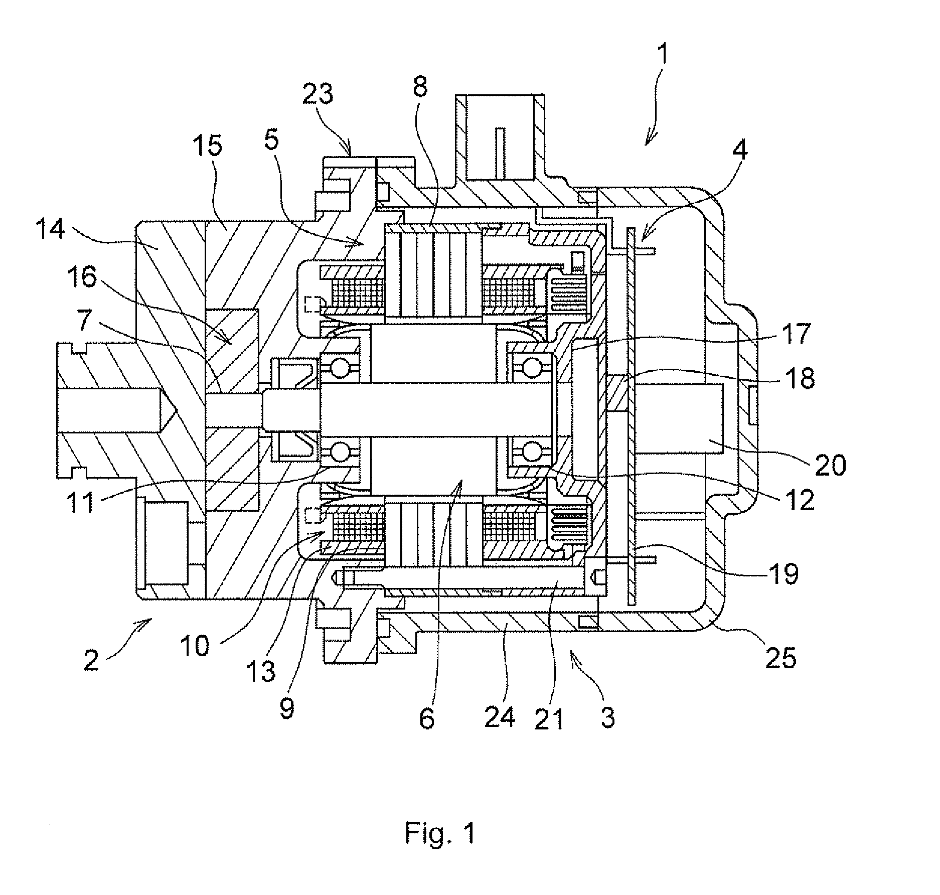
[0016]FIG. 1 is an axial sectional view showing the structure of an electric oil pump device 1 according to an embodiment of the invention. As shown in FIG. 1, the electric oil pump device (the electric unit) 1 is used as a hydraulic pump for an automobile transmission. In the electric oil pump device 1, an oil pump (e.g. an internal gear pump) 2 and an electric motor (hereinafter, referred to as “brushless motor”) 3 that rotates the oil pump (an example of “rotated member” in the invention) 2 are arranged side by side and assembled together. In addition, a controller 4 is incorporated in a motor housing 24. The brushless motor 3 shown in FIG. 1 is a brushless sensor-less motor that includes three-phase coils.

[0017]In the present embodiment, a trochoid pump is used as the oil pump 2. An inner rotor for a pump (hereinafter, referred to as “inner rotor”) (not shown) that has e...


PUM


Abstract

A pump housing, a fixing member and a holding member are assembled in the axis direction of an oil pump to fix a stator and a rotor of a brushless motor. The holding member is made of metal material and has a cylindrical shape that extends from its bottom portion toward one side in the axial direction. The fixing member is a cylindrical metal member. Stepped portions, extending in the circumferential direction, are formed in the outer periphery of the holding member and the inner periphery of the fixing member, and contact each other. The outer periphery of the holding member engages with the inner periphery of the fixing member. The outer periphery of the other end portion of the fixing member is fitted to the inner periphery of a flange portion projecting from the end face of the pump housing, which is adjacent to the brushless motor.

Description

INCORPORATION BY REFERENCE / RELATED APPLICATION[0001]This application claims priority to Japanese Patent Application No. 2011-257481 filed on Nov. 25, 2011 the disclosure of which, including the specification, drawings and abstract, is incorporated herein by reference in its entirety.BACKGROUND OF THE INVENTION[0002]1. Field of the Invention[0003]The invention relates to an electric motor and an electric unit including the electric motor.[0004]2. Discussion of Background[0005]There is a conventional electric oil pump device that is formed by assembling together an oil pump that circulates fluid (oil) and an electric motor that drives the oil pump. As such an electric oil pump device, Japanese Patent Application Publication No. 2006-274921 (JP 2006-274921 A) suggests an electric oil pump device in which an electric motor and an oil pump are arranged side by side along the direction of the central axis of the oil pump and accommodated together in a common housing.[0006]The electric oil...

Claims


Application Information

Patent Timeline
Patent Type & Authority Applications(United States)
IPC IPC(8): F04D13/06
CPCF04D13/06H02K1/185H02K5/15H02K15/16H02K7/1166H02K7/14H02K5/1732F04C2240/805
Inventor KANDA, NAOTAKEOONO, YOSHIHIRO
Owner JTEKT CORP
Why Eureka
Try Eureka