Co-current mixer, apparatus, reactor and method for precipitating nanoparticles

a technology of mixer and nanoparticle, which is applied in the direction of supercritical condition process, separation process, bulk chemical production, etc., can solve the problems of particle residue, and achieve the effect of reducing the number of processing steps

Active Publication Date: 2013-05-30
UCL BUSINESS PLC
View PDF3 Cites 12 Cited by
  • Summary
  • Abstract
  • Description
  • Claims
  • Application Information

AI Technical Summary

Benefits of technology

[0036]The quenching and chemical treatment aspects may be combined so that nanoparticles in the outflow are both of a desired size range and have a desired constitution. This feature of the invention may reduce the number of processing steps which are required to synthesize functionalized nanomaterials.

Problems solved by technology

In the second case oxidization may result in a particulate residue.

Method used


Image

  • Co-current mixer, apparatus, reactor and method for precipitating nanoparticles
  • Co-current mixer, apparatus, reactor and method for precipitating nanoparticles
  • Co-current mixer, apparatus, reactor and method for precipitating nanoparticles

Examples


Embodiment Construction

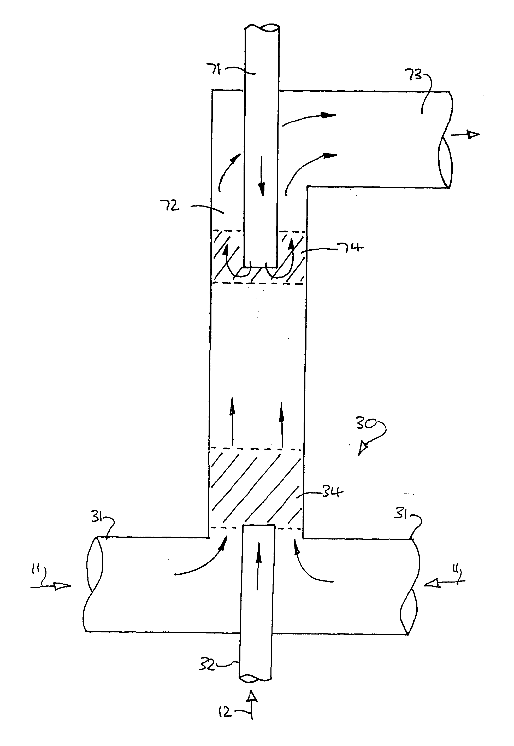
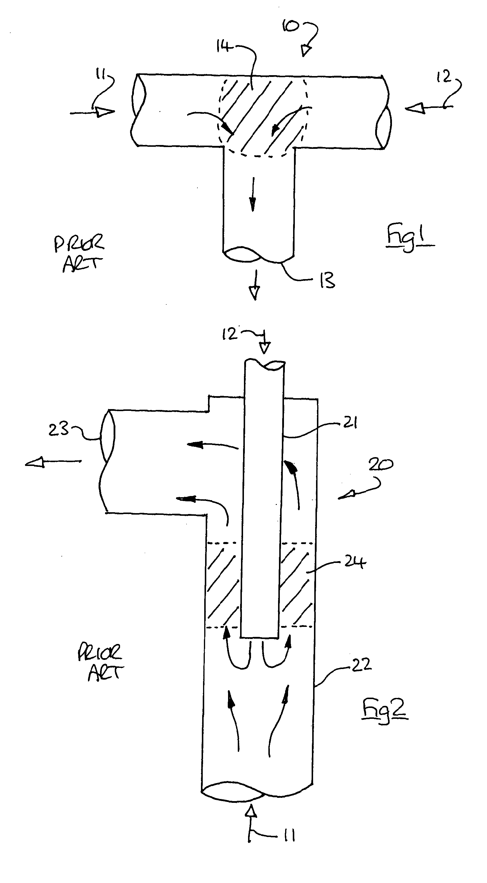
[0048]FIG. 1 illustrates a conventional ‘Tee’ shaped mixer (10) in which a flow precursor (11), typically a metal salt solution opposes a counterflow of supercritical water (12). The respective flows meet at a mixing zone (14) in the vicinity of the ‘T’ junction, and flow out at right angles to an outlet (13), as indicated by the arrows.

[0049]Under ideal conditions, the reaction of the inlet flows causes precipitation and growth of nanoparticles in the mixing zone, and the outlet flow comprises an aqueous suspension of nanoparticles from which the solids are subsequently separated for further processing.

[0050]In the mixer of FIG. 1, the precise location of precipitation is difficult to control, with the result that the mixing zone may migrate towards the precursor source. In these circumstances nanoparticles will be precipitated in the precursor inlet tract, and a blockage will typically occur as the mass flow of precursor reduces. As a consequence the reaction must be stopped, and ...


PUM


Abstract

A high pressure tubular reactor for production of nanoparticles by precipitation has unidirectional fluid flows of precursor and supercritical water directed from inner and outer coaxial inlets to an outlet via a reaction zone immediately downstream of the inlets. The inner inlet is for supercritical fluid, and the outer inlet is for a precursor.

Description

CROSS-REFERENCE TO RELATED APPLICATIONS[0001]This application claims priority to International Application Serial No. PCT / GB2011 / 000750, filed May 17, 2011, which claims priority to GB Application No. 1008721.1 filed May 25, 2010, and GB Application No. 1013063.1, filed Aug. 3, 2010. International Application Serial No. PCT / GB2011 / 000750 is hereby incorporated herein for all purposes by this reference.FIELD OF THE INVENTION[0002]The present invention relates to a mixer for fluid materials, and particularly to a mixer suitable for rapidly combining an aqueous solution or suspension of solid particles (also referred to as a precursor) at room temperature with pure water at an elevated temperature and pressure, in a continuous hydrothermal process.[0003]The present invention is suitable for continuous production of nanoparticles as an aqueous suspension.BACKGROUND[0004]The use of semi-continuous or continuous systems utilising different fluids (e.g. carbon dioxide) in their supercritic...

Claims


Application Information

Patent Timeline
Patent Type & Authority Applications(United States)
IPC IPC(8): B01J8/00
CPCB01D11/0411B01F5/045B01F13/0059B82Y99/00B01J3/008B01J3/02B01J8/005B01F2005/0034B01J19/0093B01J2219/00889Y02P20/54B01F2025/918B01F25/313B01F33/30
Inventor DARR, JAWWADTIGHE, CHRISTOPHER JAMESGRUAR, ROBERT
Owner UCL BUSINESS PLC
Why Eureka
Try Eureka