Multi-Tube Biofilter System for Treating Waste Gas

Active Publication Date: 2013-05-30
YANG CHUNPING
View PDF9 Cites 9 Cited by
  • Summary
  • Abstract
  • Description
  • Claims
  • Application Information

AI Technical Summary

Benefits of technology

[0010]The technical problems to be solved by the present invention are as follows: in response to the technical problems in the prior art, the present invention is to provide a simple, compact, low cost, and easy to operate and maintain multi-tube biofilter s

Problems solved by technology

In the recent years of industrial production, the consumption of organic fuel has been dramatically increased, which relatively produces large amount of malodorous gases and volatile organic compounds (VOCs).
Most of these VOCs are characterized with a pungent smell, and are the cause of adverse environmental damage such as atmospheric pollution, crop failures, and the destruction of the forest, in addition to being harmful to humans.
However, it has following disadvantages, such as large footprint, uneven air distribution, and unstable performance over a long operation duration.
Special difficulties associated with this process are medium bed clogging, increased drop of pressure and deterioration in the removal caused by high degree of clogging when the conventional biofilter has been run for a long time.
Whereas, the biotrickling filter has several disadvantages, such as medium clogging resulted by excess accumulati

Method used


Image

  • Multi-Tube Biofilter System for Treating Waste Gas
  • Multi-Tube Biofilter System for Treating Waste Gas
  • Multi-Tube Biofilter System for Treating Waste Gas

Examples


Example

[0041]The following description is disclosed to enable any person skilled in the art to make and use the present invention. Preferable embodiments are provided in the following description only as examples and modifications will be apparent to those skilled in the art. The general principles defined in the following description would be applied to other embodiments, alternatives, modifications, equivalents, and applications without departing from the spirit and scope of the present invention.

[0042]Referring to the drawings and the embodiments, the present invention is further described in detail as follows.

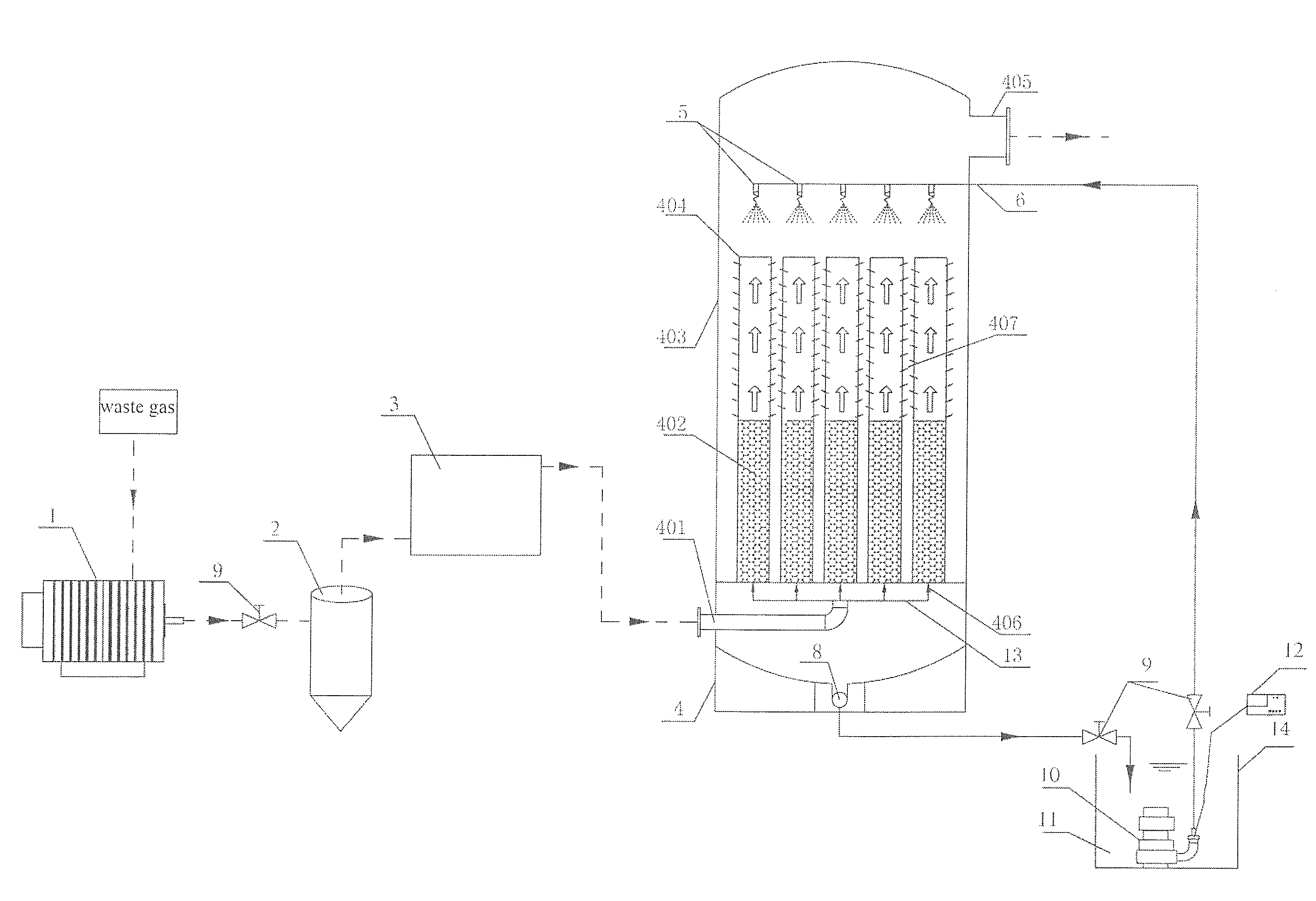
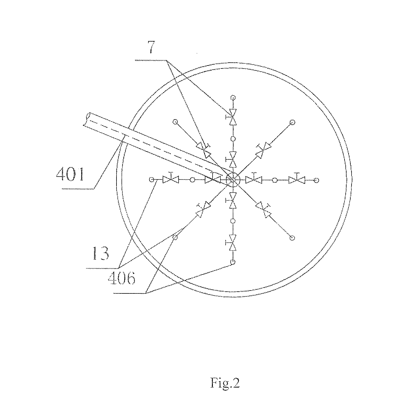
[0043]The first preferred embodiment, as shown in FIG. 1, FIG. 2, FIG. 3 and FIG. 4, is a multi-tube biofilter system for treating waste gas, wherein the multi-tube biofilter system comprises a multi-tube biofilter 4 and a nutrient solution supply system 14. The multi-tube biofilter 4 further comprises an outer casing 403, at least two reticulated tubes 404 provided in the outer c...


PUM


Abstract

Disclosed is a multi-tube biofilter system for treating waste gas. The multi-tube biofilter system includes a multi-tube biofilter and a nutrient solution supply system. The multi-tube biofilter includes an outer casing, at least two reticulated tubes disposed in the outer casing, a packing medium portion, and a nutrient solution spraying system. The outer casing is opened to define a gas inlet, a gas outlet, and a water outlet therein. The packing medium portion is attached to an outer surface of each of the reticulated tubes, wherein a liquid entering end of the nutrient solution spraying system is in communication with the nutrient solution supply system via a pipeline, and solution spraying ends of the nutrient solution spraying system face the reticulated tubes.

Description

BACKGROUND OF THE PRESENT INVENTION[0001]1. Field of Invention[0002]The present invention relates to the field of treatment devices for low concentration waste gas, and more particular to a biofilter system for treating malodorous or low concentration organic waste gas.[0003]2. Description of Related Arts[0004]In the recent years of industrial production, the consumption of organic fuel has been dramatically increased, which relatively produces large amount of malodorous gases and volatile organic compounds (VOCs). These VOCs not only increases in volume and variety, but also emits in different sites. Most of these VOCs are characterized with a pungent smell, and are the cause of adverse environmental damage such as atmospheric pollution, crop failures, and the destruction of the forest, in addition to being harmful to humans. It is no wonder why VOCs have aroused a widespread concern.[0005]There are a number of technologies for controlling these malodorous gases or VOCs, such as ab...

Claims


Application Information

Patent Timeline
IPC IPC(8): C12M1/12
CPCB01D53/85C12M25/14B01D2257/708Y02A50/20
Inventor YANG, CHUNPINGYANG, HAININGCHEN, HONGYU, GUANLONGZENG, GUANGMINGLUO, SHENGLIAN
Owner YANG CHUNPING
Why Eureka
Try Eureka