Liquid crystal display device

a liquid crystal display and display device technology, applied in the field of liquid crystal display devices, can solve the problems of led pcb malfunction, fragile connection between flexible cable and led pcb, damage to driving parts, etc., and achieve the effect of increasing the reliability of the lcd device and preventing damage to circuit components

Active Publication Date: 2013-06-06
LG DISPLAY CO LTD
View PDF11 Cites 18 Cited by
  • Summary
  • Abstract
  • Description
  • Claims
  • Application Information

AI Technical Summary

Benefits of technology

[0014]Embodiments relate to a liquid crystal display (LCD) device including a flexible printed circuit board (FPCB) where a first portion for mounting a plurality of light emitting diodes (LEDs) is integrated into a single body with a second portion that extends from the first portion and is bent to electrically connect the FPCB to a circuit for operating the plurality of LEDs. By integrating the first portion and the second portion, disconnection between the FPCB and the circuit is unlikely to occur, increasing the reliability of the LCD device and preventing damages to circuit components of the LCD device.

Problems solved by technology

However, the backlight unit 20 having the above-mentioned structure has several problems.
First, connection between the flexible cable and the LED PCB 29b is fragile.
This may cause malfunction of the LEDs 29a or damage to driving parts.
In addition, there may be soldering problems such as cold solder or insufficient solder between the LED PCB 29b and the flexible cable, which may also cause malfunction of the LEDs 29a or damage the driving parts.

Method used


Image

  • Liquid crystal display device
  • Liquid crystal display device
  • Liquid crystal display device

Examples


Embodiment Construction

[0028]Reference will now be made in detail to embodiments of the present invention, examples of which are illustrated in the accompanying drawings.

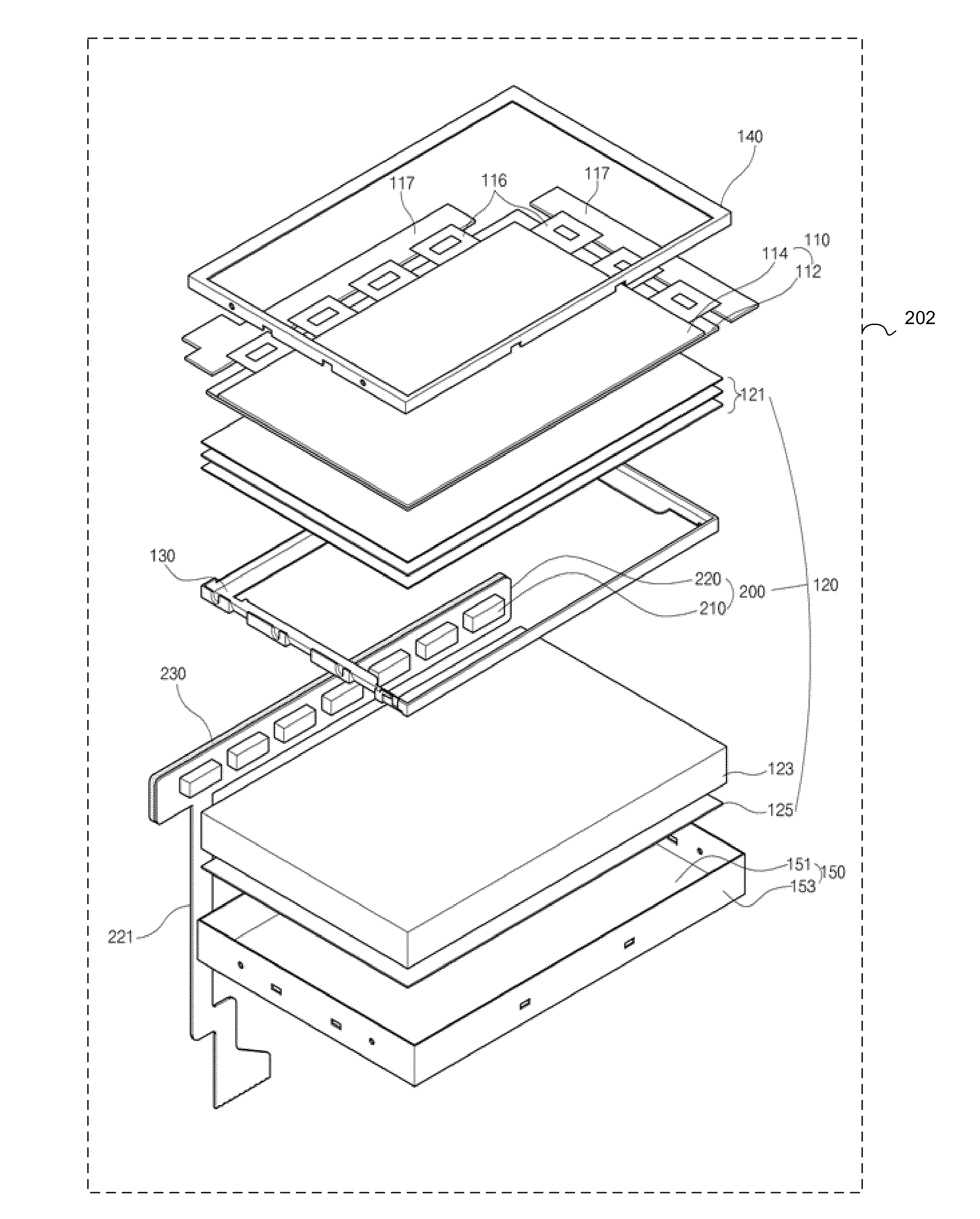
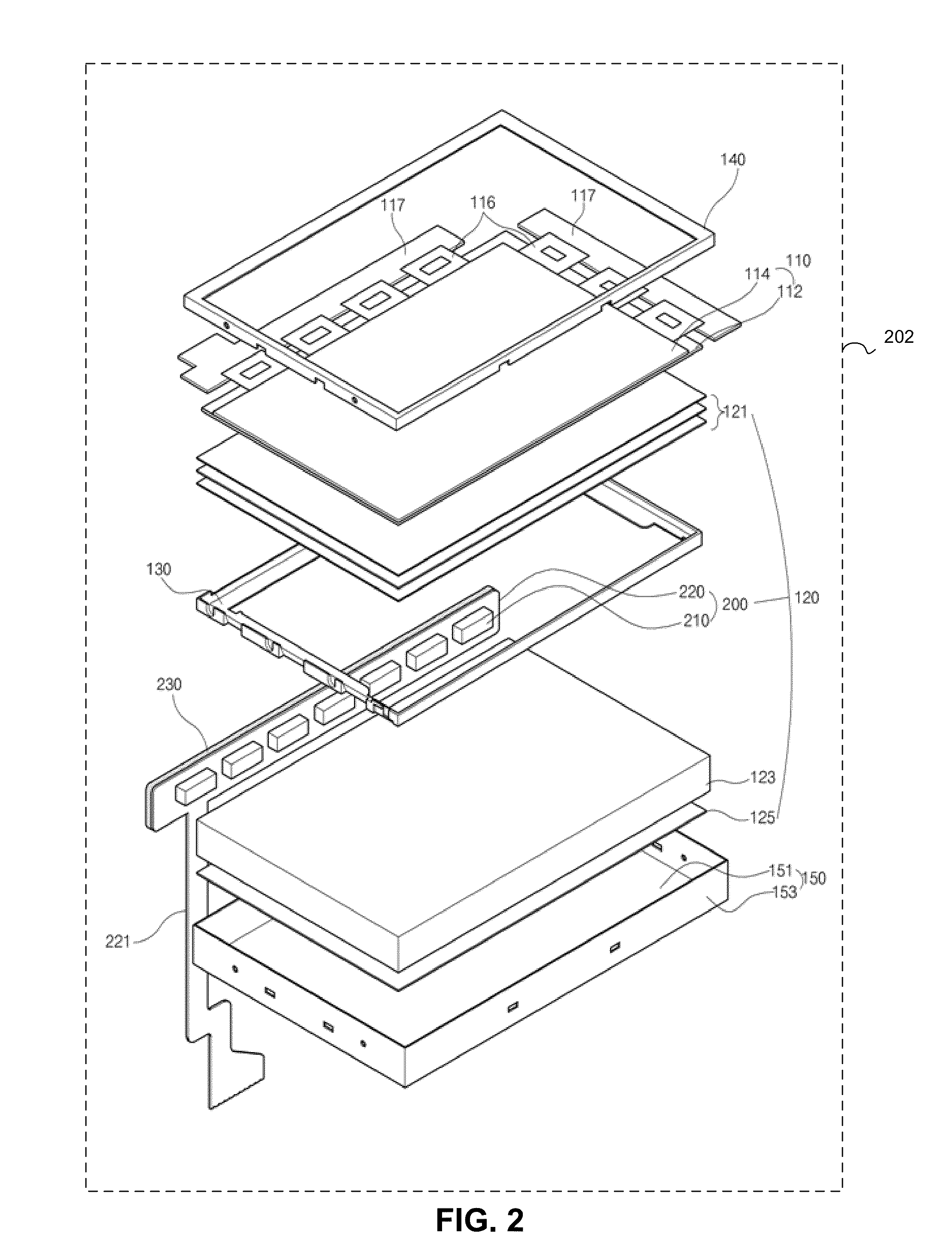
[0029]FIG. 2 is an exploded perspective view illustrating an LCD device 202 according to an example embodiment. In FIG. 2, the LCD device 202 includes a liquid crystal panel 110, a backlight unit 120, a support frame 130, a top cover 140 and a bottom cover 150.

[0030]More particularly, the liquid crystal panel 110 displays images. The liquid crystal panel 110 includes first and second substrates 112 and 114 facing and attached to each other with a liquid crystal layer placed between the first and second substrates 112 and 114. In an active matrix-type (although not shown in the figures), gate lines and data lines are formed on an inner surface of the first substrate 112. The first substrate 112 may also be referred to as a lower substrate or an array substrate. The gate lines and the data lines intersect to define pixel regions.

[0031]A thi...


PUM

PropertyMeasurementUnit
angleaaaaaaaaaa
rigidityaaaaaaaaaa
flexibleaaaaaaaaaa

Abstract

A liquid crystal display device includes a reflection plate; a light guide plate over the reflection plate; a light-emitting diode (LED) assembly including LEDs arranged along a side surface of the light guide plate, an LED flexible printed circuit board (FPCB) having LEDs mounted on its surface. The FPCB includes a bar and a leg portion extending from the body. The bar and the leg portion are integrated into a single body. The leg portion extends from the bar to a circuit for controlling the LEDs. A metallic bar is attached to bar of the LED FPCB to provide rigidity to the FPCB as well as cool the FPCB.

Description

RELATED APPLICATIONS[0001]This application claims priority to Korean Patent Application No. 10-2011-0129681, filed on Dec. 6, 2011, which is hereby incorporated by reference.BACKGROUND[0002]1. Field of The Disclosure[0003]This disclosure relates to a liquid crystal display device, and more particularly, to a connection structure between a flexible cable and a light-emitting diode (LED) assembly functioning as a light source in a liquid crystal display device.[0004]2. Discussion of The Related Art[0005]Liquid crystal display (LCD) devices are widely used as monitors of notebook computers, monitors of personal computers and televisions due to excellent reproduction of moving images and high contrast ratio. LCD devices use the optical anisotropy and polarization properties of liquid crystal molecules of a liquid crystal layer to produce an image.[0006]An LCD device includes two substrates spaced apart from each other and facing each other as well as a liquid crystal layer interposed be...

Claims


Application Information

Patent Timeline
Patent Type & Authority Applications(United States)
IPC IPC(8): G02F1/1335
CPCG02B6/0083G02F1/133615G02B6/0085G02F1/1333
Inventor SON, YOUNG-UK
Owner LG DISPLAY CO LTD
Why Eureka
Try Eureka