
Fluid control device

a control device and fluid technology, applied in the direction of positive displacement liquid engines, valve operating means/release devices, machines/engines, etc., can solve the problem of excessive load on the motor, and achieve the effect of simple configuration

Inactive Publication Date: 2013-06-06
CKD
View PDF1 Cites 19 Cited by
  • Summary
  • Abstract
  • Description
  • Claims
  • Application Information

AI Technical Summary

Benefits of technology

The present invention aims to prevent the valve body from being forcefully pressed against the valve seat and to reduce the excessive load on the motor in a fluid control device.

Problems solved by technology

In this case, the valve body may be pressed forcefully against a valve seat or the like, and an excessive load may be exerted on the motor when feeding of the female screw member is restricted.

Method used


Image

  • Fluid control device
  • Fluid control device
  • Fluid control device

Examples


Embodiment Construction

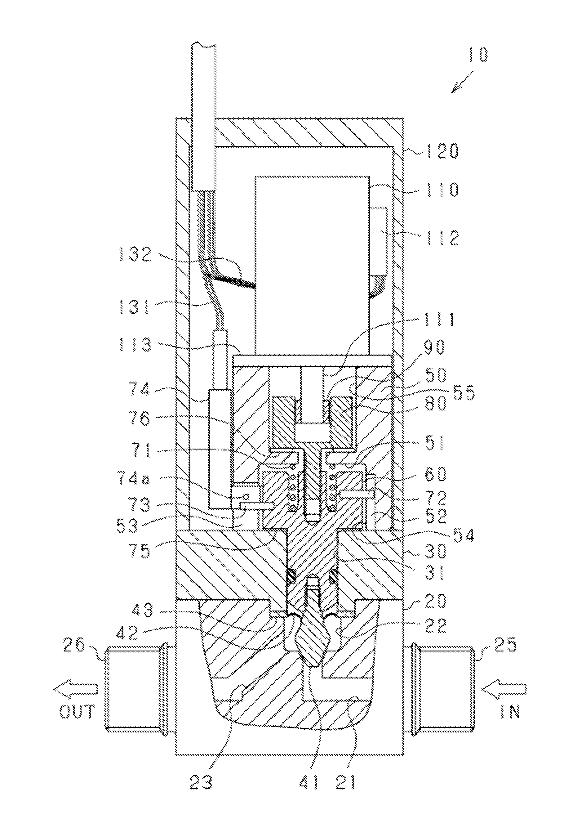
[0031]An embodiment will be described below with reference to the drawings. In this embodiment, the present invention is realized as a flow rate adjustment device that adjusts a flow rate of a fluid in a semiconductor manufacturing apparatus or the like.

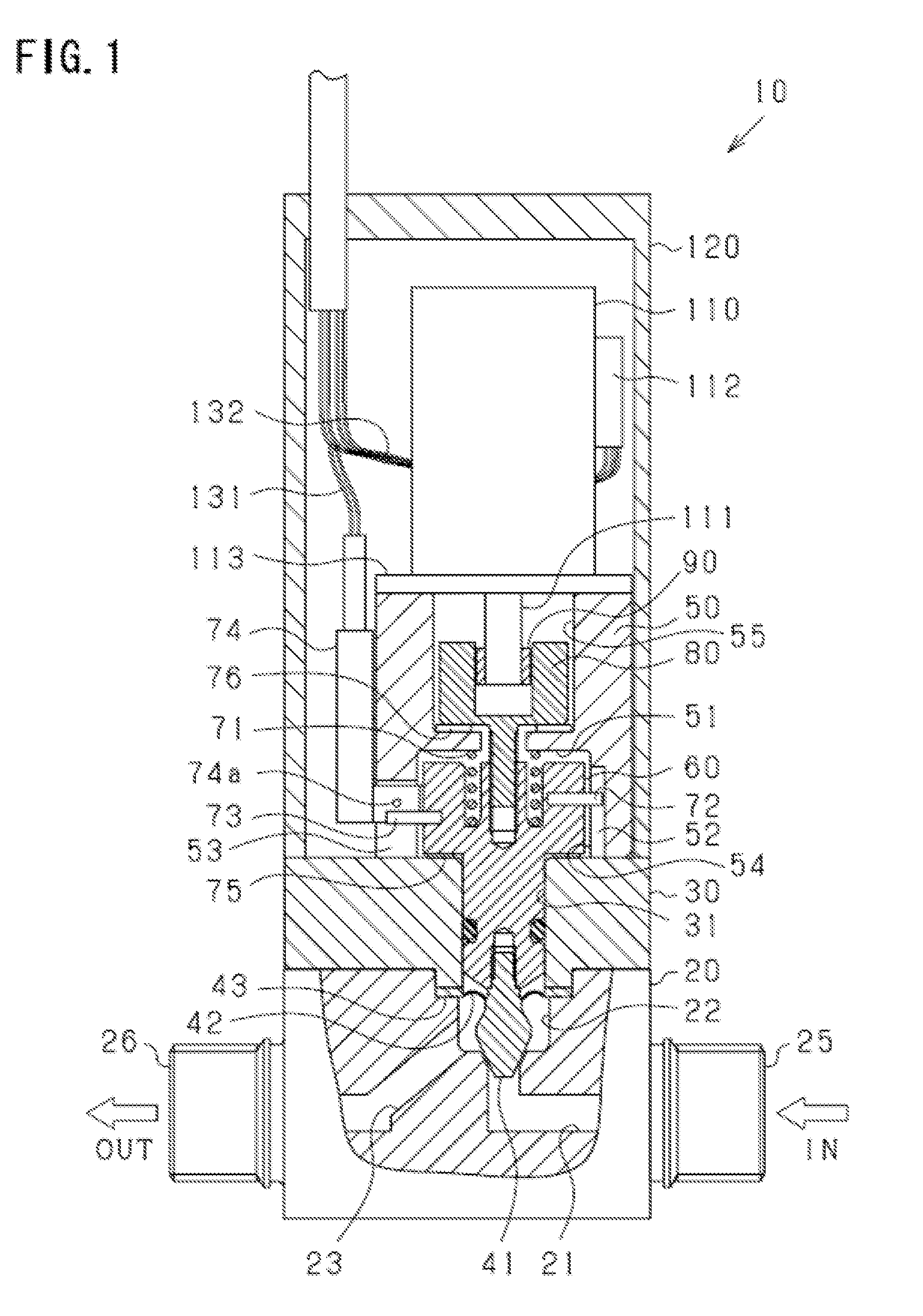
[0032]FIG. 1 is a partial sectional view showing a flow rate adjustment device 10. The flow rate adjustment device 10 (fluid control device) includes a valve main body 20, a first cylinder 30, a second cylinder 50, a motor 110, and a housing 120.

[0033]The valve main body 20 is provided with an inflow port 25 through which a fluid (a liquid) flows in, and an outflow port 26 through which the fluid flows out. The valve main body 20 is formed of a chemical-resistant fluorine resin, for example PTFE (Poly Tetra Fluoro Ethylene). A flow passage 21 connected to the inflow port 25, a flow passage 23 connected to the outflow port 26, and a valve chamber 22 that connects the flow passages 21 and 23 are formed in an interior of the valve main ...


PUM


Abstract

In a fluid control device, a valve body is prevented from being pressed forcefully against a valve seat or the like, and an excessive load is prevented from acting on a motor. A flow rate adjustment device includes a first engagement portion, and a second engagement portion that is capable of moving relative to the first engagement portion and transmitting and receiving rotary force. The flow rate adjustment device includes a valve body that adjusts an opening of a flow passage, and a rod that is coupled to the valve body. The flow rate adjustment device further includes a male screw portion and a female screw portion that are intermeshed so as to be fed relative to each other in the axial direction, a projecting portion that restricts movement of the second engagement portion, and a first cylinder that restricts movement of the rod.

Description

BACKGROUND OF THE INVENTION[0001]1. Field of the Invention[0002]The present invention relates to a fluid control device that controls a position of a valve body on the basis of rotation of a motor.[0003]2. Description of the Related Art[0004]In a conventional fluid control device of this type, a position of the valve body in an open condition is determined by rotating a male screw member coupled to a drive shaft of the motor such that a female screw member meshed to the male screw member is fed in an axial direction of the male screw member (see Patent Documents 1 and 2, for example). In the devices described in Patent Documents 1 and 2, a stop position of the valve body in the open condition is determined when a piston coupled to the valve body impinges on the female screw member.[0005]Patent Document 1: Japanese Patent Application Publication No. 2003-083466[0006]Patent Document 2: Japanese Patent Application Publication No. 2007-278514[0007]Incidentally, with the devices describe...

Claims


Application Information

Patent Timeline
IPC IPC(8): F04B27/00
CPCF16K31/046F16K41/103F16K31/508F16K31/04F16K31/124F16K35/00G05D7/06
Inventor NABEI, TATSUSHINAKAMURA, YUKIE
Owner CKD
Features
  • Generate Ideas
  • Intellectual Property
  • Life Sciences
  • Materials
  • Tech Scout
  • Unparalleled Data Quality
  • Higher Quality Content
  • 60% Fewer Hallucinations
Learn More