Spine stabilization system

a stabilizing system and spine technology, applied in the field of orthopaedic surgical devices, can solve the problems of limiting the range of motion of the spine, affecting the function of the nervous system, and affecting the ability of the spine to move freely, so as to facilitate the bending of the rod

Active Publication Date: 2013-06-06
K2M
View PDF62 Cites 34 Cited by
  • Summary
  • Abstract
  • Description
  • Claims
  • Application Information

AI Technical Summary

Benefits of technology

[0016]Bending the connecting rod may include inserting the connecting rod through an aperture in each of the pair of rod bending devices and applying leveraged force to the connecting rod through the handle members of the rod bending devices. Bending the connecting rod may include bending the connecting rod in an anterior-posterior orientation. Bending the connecting rod may include bending the connecting rod in a medial-lateral orientation. Providing multiple apertures in the rod bending devices facilitates bending the rod by permitting the rod to be oriented in various positions relative to the handles.

Problems solved by technology

There are various disorders, diseases and types of injury, which restrict the range of motion of the spine or interfere with important elements of the nervous system.
Persons suffering from any of the above conditions typically experience extreme or debilitating pain and often times diminished nerve function.
These conditions and their treatments can be further complicated if the patient is suffering from osteoporosis, or bone tissue thinning and loss of bone density.
However when large deformity corrections need to be made, these rods are not always strong enough.
In addition, in order to reduce the likelihood of material incompatibility in vivo, the screw assembly also needs to be made of stainless steel to match the rod material, which is not a cost effective alternative.

Method used


Image

  • Spine stabilization system
  • Spine stabilization system
  • Spine stabilization system

Examples


Embodiment Construction

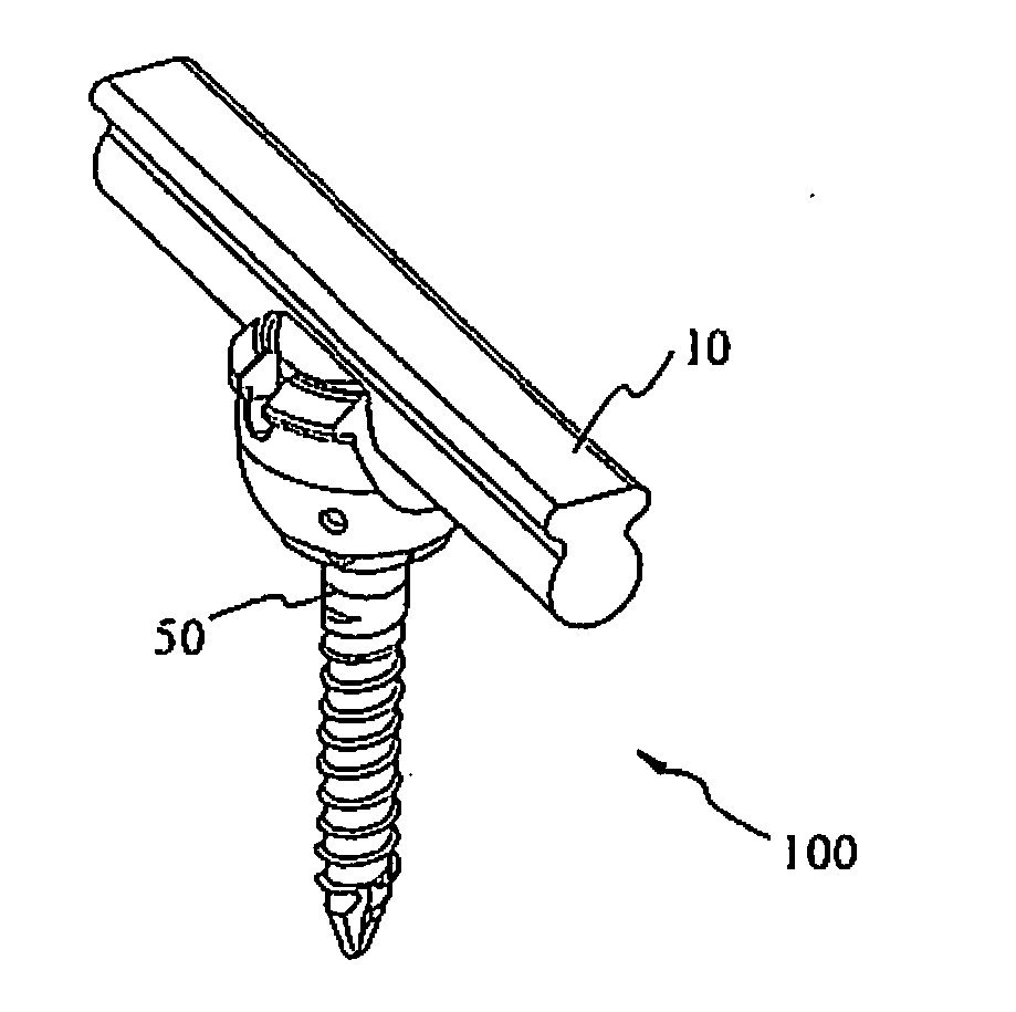
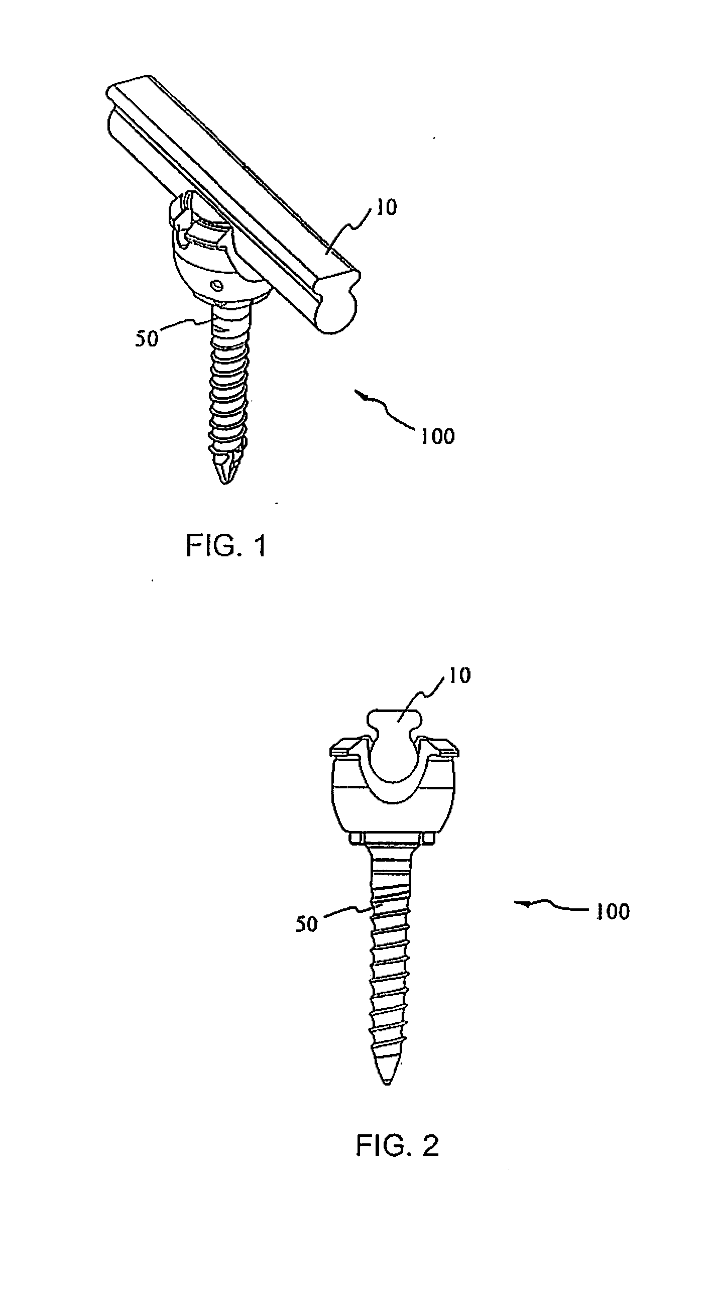
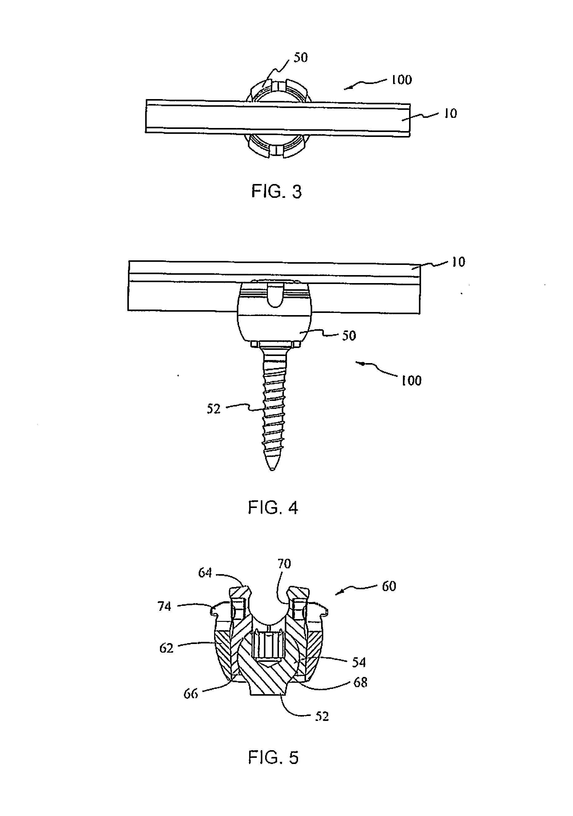
[0081]Embodiments of the present disclosure will now be described in detail with reference to the drawings, in which like reference numerals designate identical or corresponding elements in each of the several views. As used herein, the term “distal,” as is conventional, will refer to that portion of the instrument, apparatus, device or component thereof which is farther from the user while, the term “proximal,” will refer to that portion of the instrument, apparatus, device or component thereof which is closer to the user. In addition, the term “cephalad” is used in this application to indicate a direction toward a patient's head, while the term “caudad” indicates a direction toward the patient's feet. Further still, for the purposes of this application, the term “medial” indicates a direction toward the middle of the body of the patient, while the term “lateral” indicates a direction toward a side of the body of the patient, i.e., away from the middle of the body of the patient. T...


PUM


Abstract

A spinal stabilization system includes a connecting rod, a rod bending device, and a plurality of bone screws. The connecting rod includes an elongate round portion, an elongate head portion and a neck portion connecting the elongate round portion with the elongate head portion. The rod bending device includes an elongate body defining an aperture configured and dimensioned to receive the connecting rod therethrough in a single orientation. The bone screws include a housing portion and a screw shaft distally extending from the housing portion. The housing portion includes an inner housing and an outer housing slidably surrounding at least a portion of the inner housing. The inner housing defines a slot configured and dimensioned to releasably secure the elongate round portion of the connecting rod therein. The outer housing is movable relative to the inner housing between an unlocked state and a locked state.

Description

CROSS-REFERENCE TO RELATED APPLICATION[0001]This application is a continuation-in-part of International Application No. PCT / US11 / 42127, filed on Jun. 28, 2011, and claims priority to, and the benefit of, U.S. Provisional Patent Application No. 61 / 359,028, filed on Jun. 28, 2010, and U.S. Provisional Patent Application No. 61 / 537,112, filed on Sep. 21, 2011, the entire contents of each of these prior applications are hereby incorporated by reference herein.BACKGROUND[0002]1. Technical Field[0003]The present disclosure relates to orthopedic surgical devices, and more particularly, to a spinal stabilization system and a method of use therefor.[0004]2. Background of Related Art[0005]The spinal column is a complex system of bones and connective tissues that provide support for the human body and protection for the spinal cord and nerves. The adult spine is comprised of an upper and lower portion. The upper portion contains twenty-four discrete bones, which are subdivided into three areas...

Claims


Application Information

Patent Timeline
Patent Type & Authority Applications(United States)
IPC IPC(8): A61B17/70
CPCA61B17/701A61B17/7035A61B17/7002A61B17/70A61B17/8863A61B17/7037A61B2017/681
Inventor STRAUSS, KEVIN R.JONES, SCOTTMOORE, JENNIFERBARRUS, MICHAELBOACHIE-ADJEI, OHENEBABOYD, ROBERT CLINTON
Owner K2M
Why Eureka
Try Eureka