
Identification of reservoir geometry from microseismic event clouds

a reservoir geometry and event cloud technology, applied in seismology for waterlogging, instruments, reradiation, etc., can solve problems such as different operation of equipment provided as an active seismic source, and achieve the effect of improving the operation

Inactive Publication Date: 2013-06-06
SCHLUMBERGER TECH CORP
View PDF5 Cites 59 Cited by
  • Summary
  • Abstract
  • Description
  • Claims
  • Application Information

AI Technical Summary

Benefits of technology

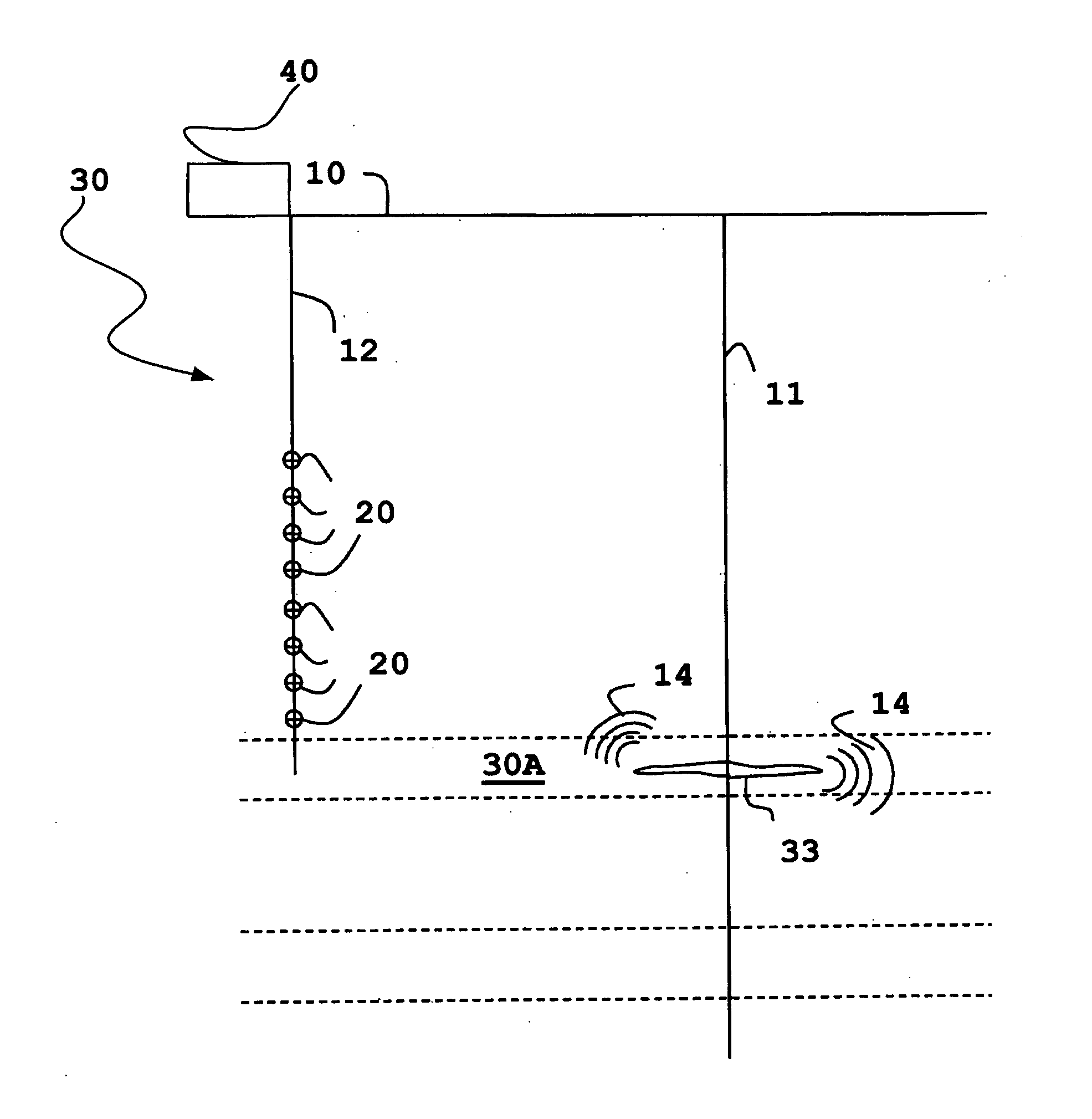
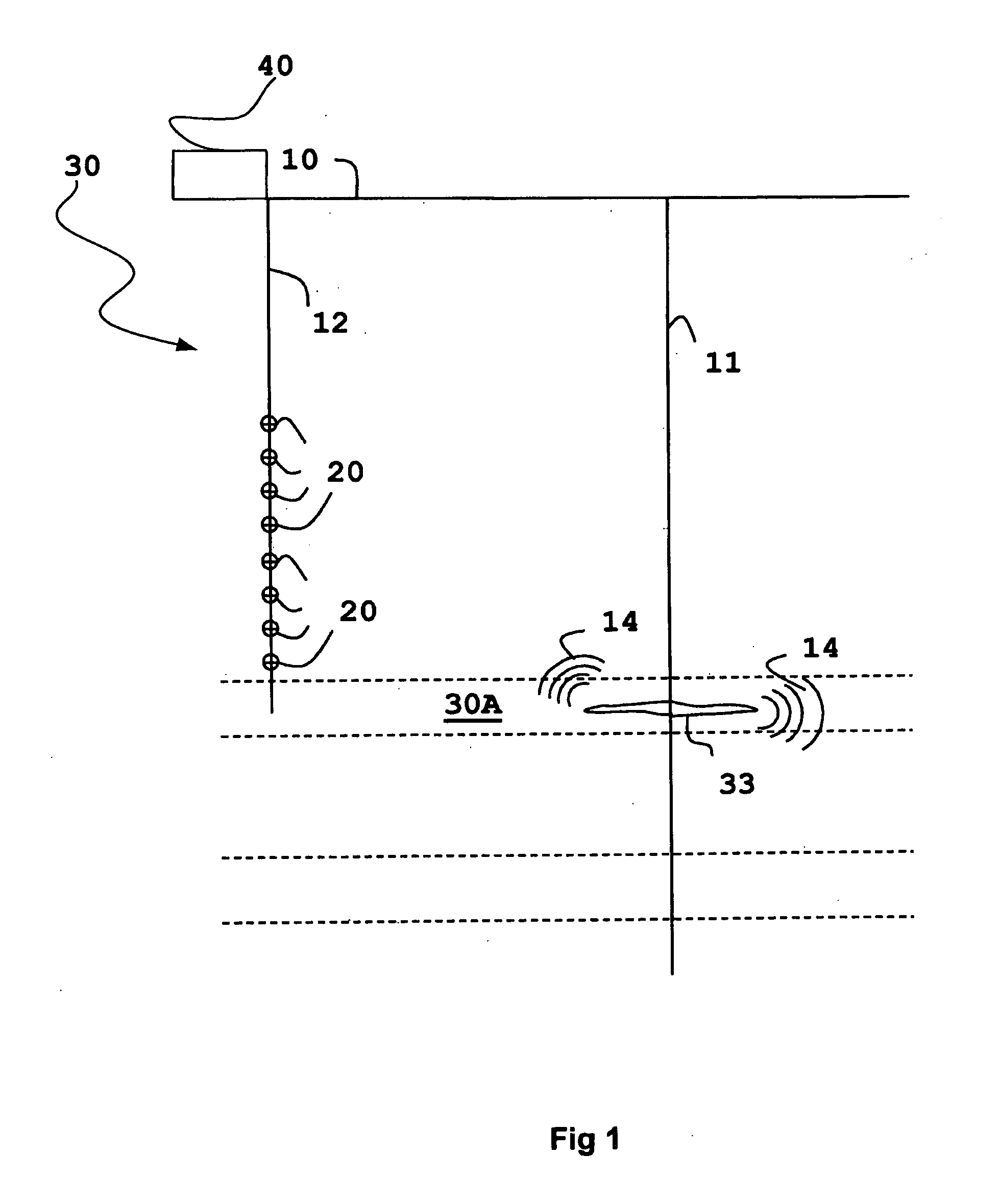
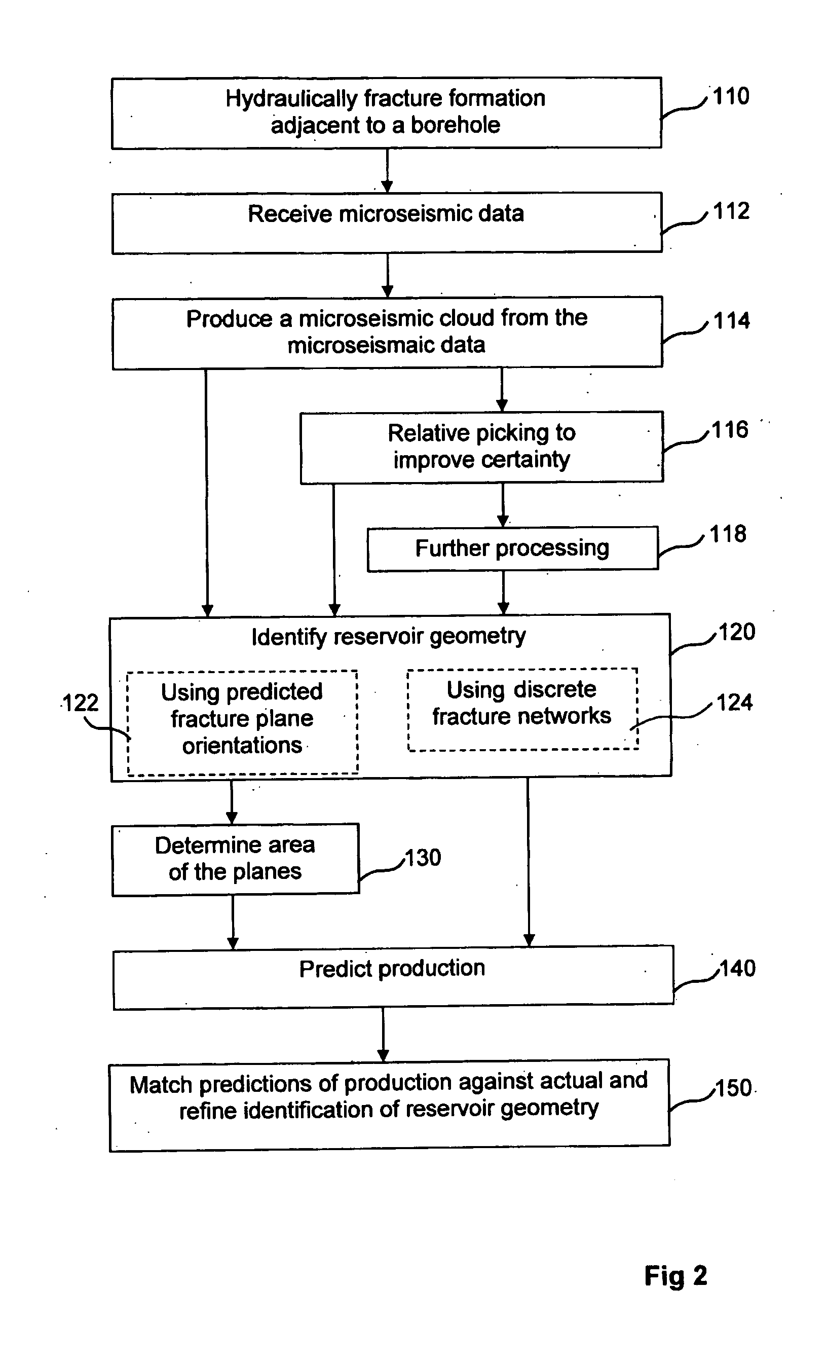
The present invention provides a method for extracting reservoir geometry or options for reservoir geometry from microseismic event clouds obtained from hydraulic fracturing processes. This allows for real-time monitoring and control of the hydraulic fracturing process. The method can identify the number and location of stimulated fracture planes generated in the hydraulic fracturing process, which can aid in the evaluation of the geometry of the fracture system. The method can also predict the production from the reservoir after fracturing and confirm the characterization of reservoir geometry or improve it by adjusting the probabilities of candidate geometries.

Problems solved by technology

Although the microseismic events may be a consequence of human activity disturbing the subterranean rock, they are quite different from operation of equipment provided as an active seismic source.
An issue with microseismic data relating to fractures in the Earth formation containing the reservoir that the data is often inconsistent with incorporation into the reservoir model.

Method used


Image

  • Identification of reservoir geometry from microseismic event clouds
  • Identification of reservoir geometry from microseismic event clouds
  • Identification of reservoir geometry from microseismic event clouds

Examples


example

[0071]As an example, a synthetic event cloud of 284 event locations was analysed as above to determine geometry. A single strike dip pair (90°, 0°) was used as predicted orientation. The error ellipsoids were projected onto a single line and the cumulation of their number density is the curve shown in FIG. 4 (the projected width of the error ellipsoids was set at 25 and it can be seen that the horizontal axis in FIG. 4 extends over a range of about 1000). The probabilities for solutions with one plane, two planes and so on up to 94 planes are plotted as a graph which is FIG. 5. It can be seen that the solutions with 2, 3, 4 and 5 planes all have similar probability, and that the probability for 6 planes is not much lower.

[0072]Calculation with several strike, dip pairs was also carried out and the candidate geometry with six large fracture planes, shown as bounded quadrilaterals, is illustrated as FIG. 6.

Geostatistical Interpretation Via DFNs

[0073]In another approach to identifying ...


PUM


Abstract

A method for characterizing fracture planes generated during a hydraulic fracturing process, comprises receiving microseismic data from the hydraulic fracturing process and processing a microseismic event cloud from the received microseismic data. This is followed by determining at least one reservoir geometry from the microseismic event cloud. The determination of geometry may consist of determining multiple candidate geometries and probability of each. In some forms of the invention the method may comprise postulating a set of candidate geometries with differing numbers of fracture planes, determining the most probable locations of the postulated fracture planes in each member of the set of candidate geometries and also determining relative probabilities of the candidate geometries in the postulated set. Determining a location of a fracture plane may comprise calculating a number density for each microseismic event, dependent on distance from some possible location of a fracture plane or fracture network. Finding the location of a plane may then be finding the location for which the number density is greatest. The determination of reservoir geometry may be followed by determination of the area of the fracture planes and / or by a prediction of production.

Description

FIELD OF THE INVENTION[0001]The present invention relates generally to the field of microseismic analysis of Earth formations. More specifically, but not by way of limitation, embodiments of the present invention relate to using microseismic analysis to characterize fractures in the Earth formation which have been created or opened by hydraulic fracturing. Some embodiments of the invention have application to hydrocarbon exploration and production where the hydrocarbon reservoir has natural fractures which can be opened in the course of fracturing, as is the case with some shale reservoirs.BACKGROUND OF THE INVENTION[0002]Microseismic measurements can be characterized as a variant of seismics. In conventional seismic explorations a seismic source placed at a predetermined location, such as one or more airguns, vibrators or explosives, is activated and generate sufficient acoustic energy to cause acoustic waves to travel through the Earth. Reflected or refracted parts of this energy ...

Claims


Application Information

Patent Timeline
IPC IPC(8): G01V1/30G01V1/50
CPCG01V1/50G01V1/301G01V2210/123G01V1/288G01V1/42G01V2210/1234G01V2210/646G01V2210/65
Inventor WILLIAMS, MICHAEL JOHNKHADHRAOUI, BASSEM
Owner SCHLUMBERGER TECH CORP
Learn More