Exposure method, exposure apparatus, and method of manufacturing device

a manufacturing method and exposure technology, applied in the field of exposure methods, can solve the problems of long alignment time of conventional methods, and achieve the effect of shortening the alignment time and improving throughpu

Inactive Publication Date: 2013-06-13
CANON KK
View PDF2 Cites 32 Cited by
  • Summary
  • Abstract
  • Description
  • Claims
  • Application Information

AI Technical Summary

Benefits of technology

The present invention provides an exposure method and exposure apparatus that can improve throughput by shortening the alignment time.

Problems solved by technology

However, the conventional method requires a long alignment time because, for prealignment, it measures the positions of two low-magnification alignment marks on each wafer to be exposed.

Method used


Image

  • Exposure method, exposure apparatus, and method of manufacturing device
  • Exposure method, exposure apparatus, and method of manufacturing device
  • Exposure method, exposure apparatus, and method of manufacturing device

Examples


first embodiment

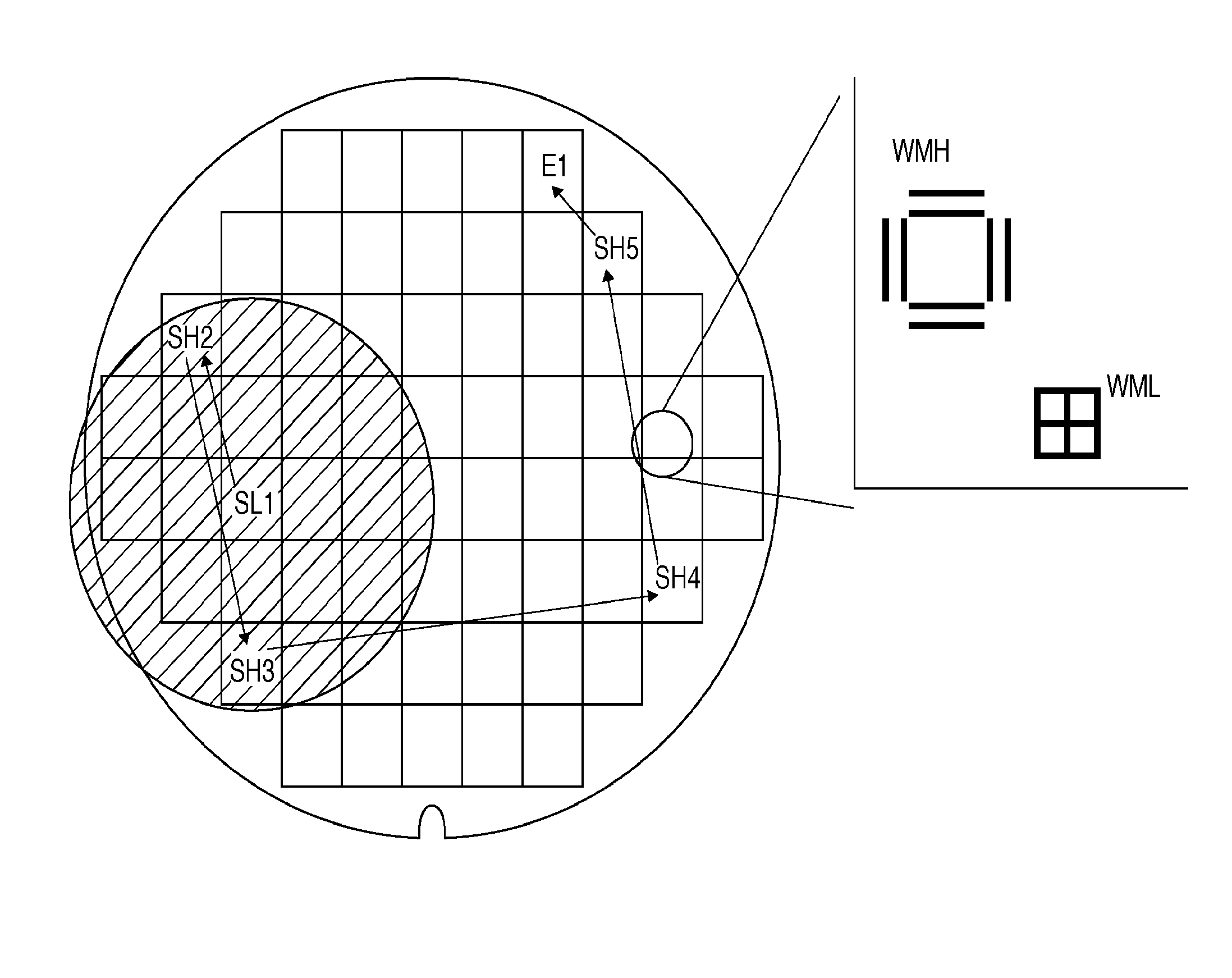
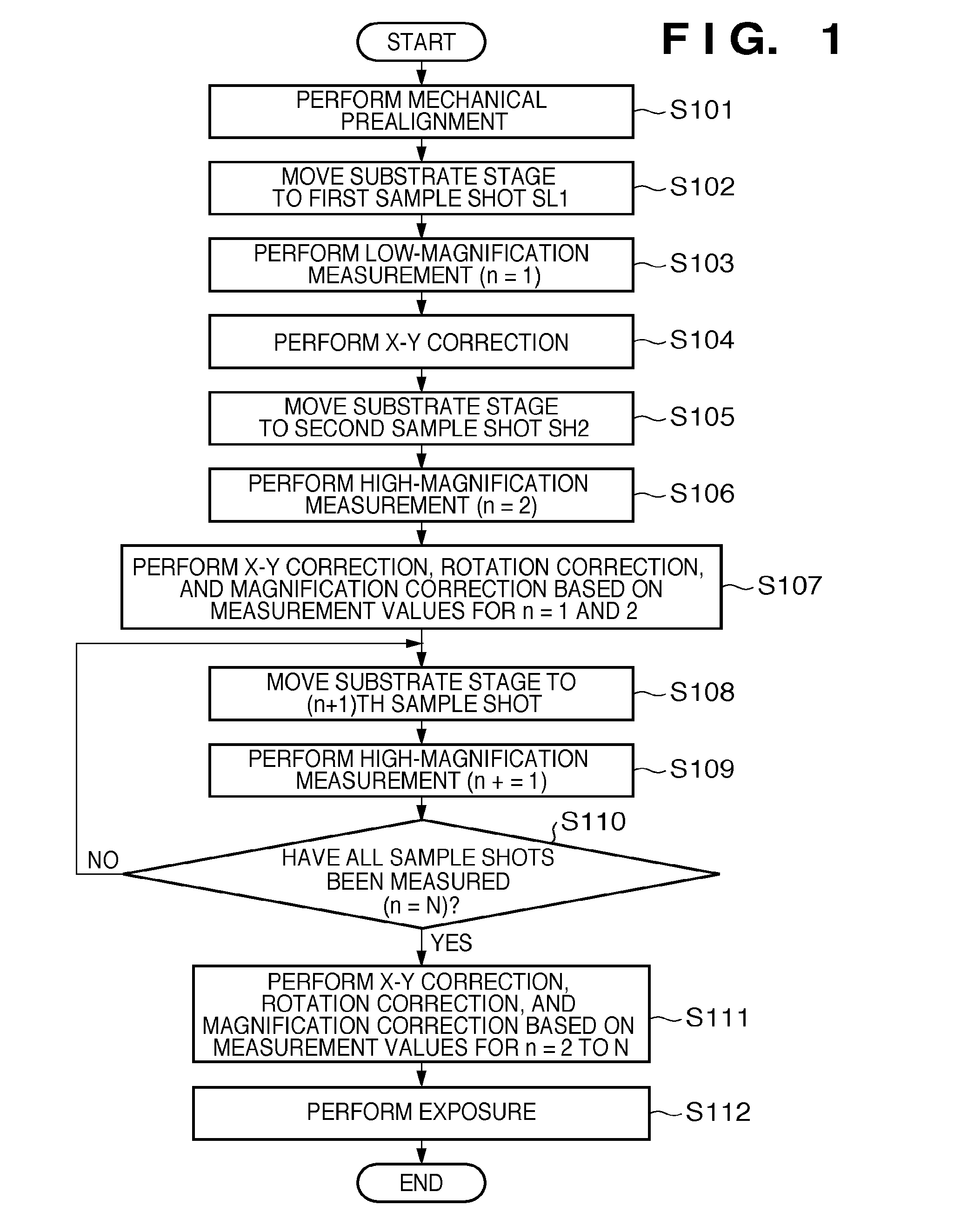
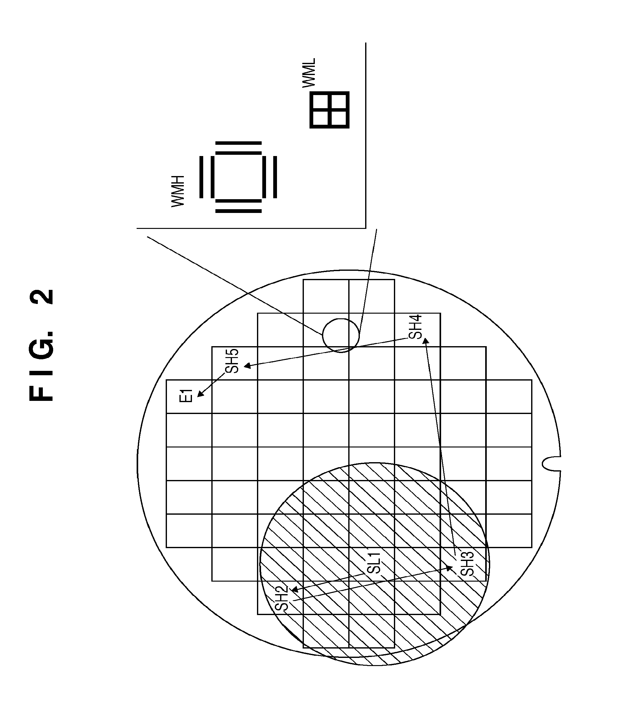
[0025]An example of alignment processing according to the present invention will be explained with reference to FIG. 1. In step S101, a controller C controls a mechanical prealignment unit (not shown) to perform mechanical prealignment of a substrate W. In this step, mechanical prealignment is performed for the wafer with reference to the notched portion and periphery of the wafer, such as an orientation flat and notch. In step S102, the controller C drives a substrate stage so that a low-magnification alignment mark WML in a first sample shot SL1, which serves as a first mark, falls within the observation range of a low-magnification scope S1 serving as a first scope with reference to the mechanical prealignment result. In step S103, the controller C controls the low-magnification scope S1 to measure the position of the low-magnification alignment mark WML in the first sample snot SL1. Step S103 is a first detection step of detecting the position of a first mark by a first scope.

[0...

second embodiment

[0036]The second embodiment relates to an exposure method of exposing a plurality of substrates by sequentially aligning them using marks formed on them.

[0037]In the first embodiment, prealignment is performed using the measurement values of the alignment marks in different sample shots, which are obtained by two scopes having different magnifications. For this reason, a prealignment correction value is often not precisely calculated in step S107 if there is an offset between the observation centers of the low-magnification scope S1 and the high-magnification scope S2 or there is a drawing offset or the like between the marks. This may make it impossible to perform high-magnification measurement subsequent to step S108. To avoid this situation, the second embodiment in which prealignment can be performed precisely even when there is an offset between the scopes or marks will be explained with reference to FIGS. 3A and 3B.

[0038]As for the first wafer, two sample shots are measured by...


PUM


Abstract

An exposure method comprises: a first detection step of detecting a position of a first mark by a first scope; a second detection step of detecting a position of a second mark by a second scope having a magnification higher than the first scope; a first calculation step of calculating a first correction value based on the detection results obtained in the first and second detection steps; a third detection step of detecting a position of a third mark by the second scope after the substrate is aligned based on the first correction value calculated in the first calculation step; a second calculation step or calculating a second correction value based on the detection results obtained in the second and third detection steps; and an exposure step of exposing the substrate after the substrate is aligned based on the second correction value calculated in the second calculation step.

Description

BACKGROUND OF THE INVENTION[0001]1. Field of the Invention[0002]The present invention relates to an exposure method, an exposure apparatus, and a method of manufacturing a device.[0003]2. Description of the Related Art[0004]Wafer processing principally includes alignment processing such as prealignment and global alignment for aligning a wafer, and exposure processing. To improve the wafer productivity, that is, the throughput, various efforts are made to shorten the time taken for each processing.[0005]In alignment processing, a plurality of marks is selected from alignment marks formed on the wafer as sample shots, and the positions of these marks are measured. The sample shots used are as shown in FIG. 4. A low-magnification alignment mark WML and high-magnification alignment mark WMH are formed in each shot. In prealignment, the position of the low-magnification alignment mark in a first sample shot SL1 is measured using a low-magnification scope first, and that of the low-magni...

Claims


Application Information

Patent Timeline
Patent Type & Authority Applications(United States)
IPC IPC(8): G01B11/14
CPCG03F9/7003G01B11/14G03F9/7046G03F7/70516G03F7/7055G03F9/7088
Inventor HAYASHI, NOZOMU
Owner CANON KK
Why Eureka
Try Eureka