Receiver optical module for receiving wavelength multiplexed optical signals and method to assemble the same

a technology of wavelength multiplexing and optical signals, applied in the field of receiving optical modules, can solve the problems of fatality of two-dimensional arrangement of optical components and obstruct the installation of optical modules

Active Publication Date: 2013-06-13
SUMITOMO ELECTRIC IND LTD
View PDF1 Cites 34 Cited by
  • Summary
  • Abstract
  • Description
  • Claims
  • Application Information

AI Technical Summary

Problems solved by technology

For such requests, the two-dimensional arrangement of the optical component becomes fatal factor to obstruct the installation of the optical module within a compact optical transceiver.

Method used


Image

  • Receiver optical module for receiving wavelength multiplexed optical signals and method to assemble the same
  • Receiver optical module for receiving wavelength multiplexed optical signals and method to assemble the same
  • Receiver optical module for receiving wavelength multiplexed optical signals and method to assemble the same

Examples


Embodiment Construction

[0020]Next, some embodiments according to the present invention will be described as referring to drawings. In the description of the drawings, numerals or symbols same or similar to each other will refer to elements same or similar to each other without overlapping explanations.

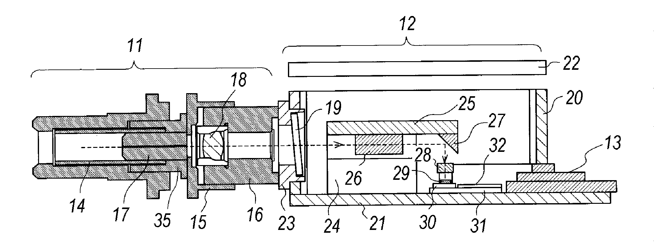
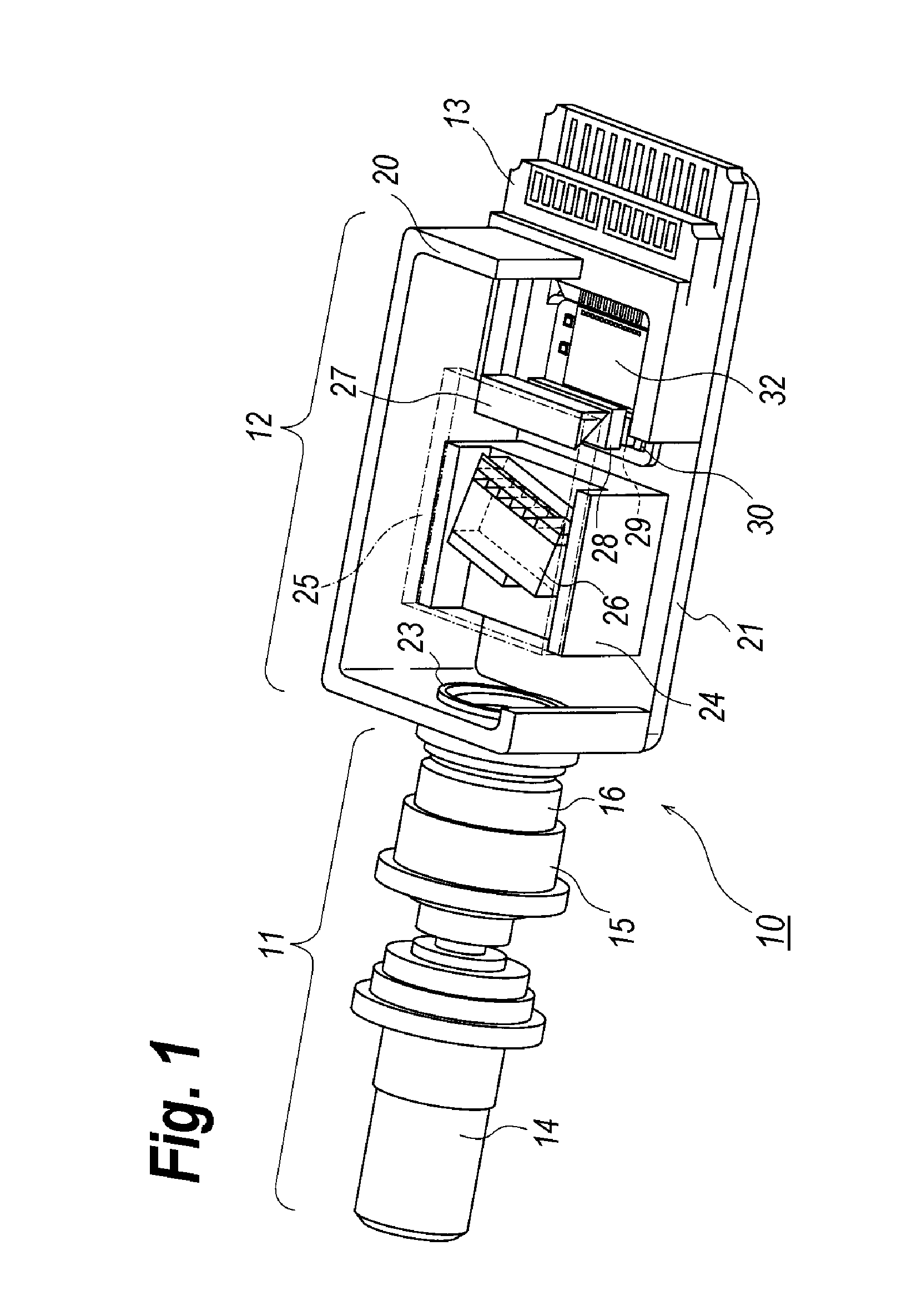
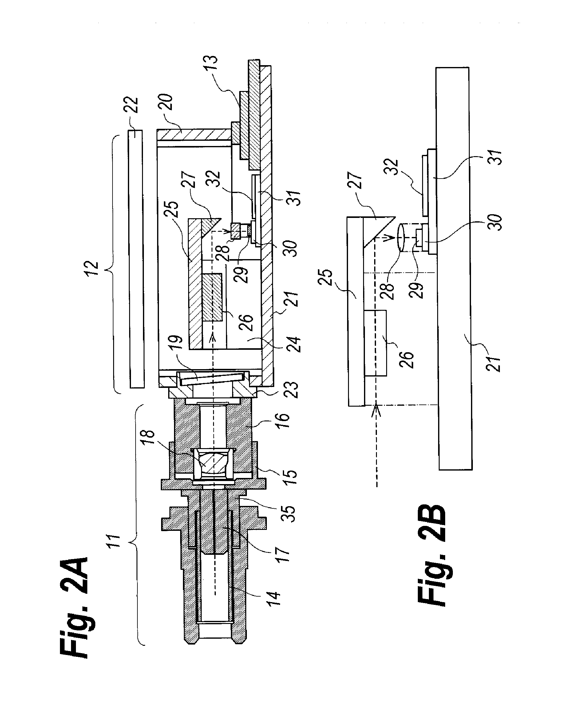
[0021]FIG. 1 is a perspective view of a receiver optical module, where a portion thereof is removed to show the inside of the module, implemented within an optical transceiver, FIG. 2A is a side cross section of the module, and FIG. 3B magnifies a primary portion to couple optical devices installed in the module with an external optical fiber.

[0022]The receiver optical module 10 shown in FIGS. 1 and 2 includes a coupling unit 11, a housing 12, and an electrical connector 13. The coupling unit 11 provides a sleeve 14, a joint sleeve 15 (hereafter denoted as J-sleeve), a joint 16, a stub 17, and a first lens 18. The housing 12, which has a box shape, provides a side 20, a bottom 21 and a lid 22. A front side 2...


PUM

PropertyMeasurementUnit
angleaaaaaaaaaa
specific wavelengthaaaaaaaaaa
wavelengthsaaaaaaaaaa

Abstract

A receiver optical module to facilitate the assembling is disclosed. The receiver optical module includes an intermediate assembly including the optical de-multiplexer and the optical reflector each mounted on the upper base, and the lens and the PD mounted on the sub-mount. The latter assembly is mounted on the bottom of the housing; while, the former assembly is also mounted on the bottom through the lower base. The upper base is apart from the bottom and extends in parallel to the bottom to form a surplus space where the amplifying circuit is mounted.

Description

BACKGROUND OF THE INVENTION[0001]1. Field of the Invention[0002]The present invention relates to a receiver optical module to be installed within an optical transceiver, in particular, the invention relates to a receiver optical module to receive wavelength multiplexed optical signals.[0003]2. Related Prior Arts[0004]The wavelength division multiplexed (WDM) system has been popular in the optical communication system. One prior patent application has disclosed an optical transceiver that implements four transmitter optical sub-assemblies (TOSA) each operable in 10 Gbps, four receiver optical sub-assemblies each operable in 10 Gbps, an optical multiplexer and an optical de-multiplexer. Such an optical transceiver has realized the transmission speed of 40 Gbps.[0005]FIG. 8A is a plan view of an optical arrangement of components which realizes the optical de-multiplexing function, while, FIG. 8B is a side view thereof. The multiplexed optical signal provided from the external optical f...

Claims


Application Information

Patent Timeline
Patent Type & Authority Applications(United States)
IPC IPC(8): H04J14/02
CPCH04J14/02G02B6/4214G02B6/4215G02B6/4292
Inventor NAKAJIMA, FUMIHIROHARA, HIROSHIFUJIMURA, YASUSHIOKI, KAZUSHIGE
Owner SUMITOMO ELECTRIC IND LTD
Why Eureka
Try Eureka