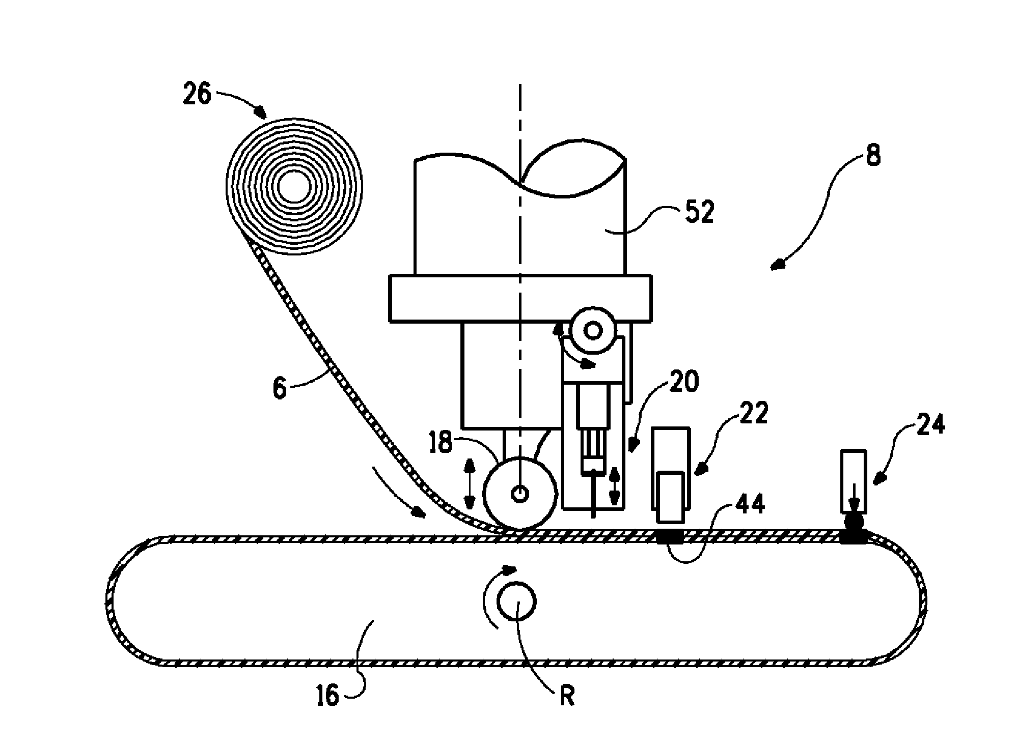
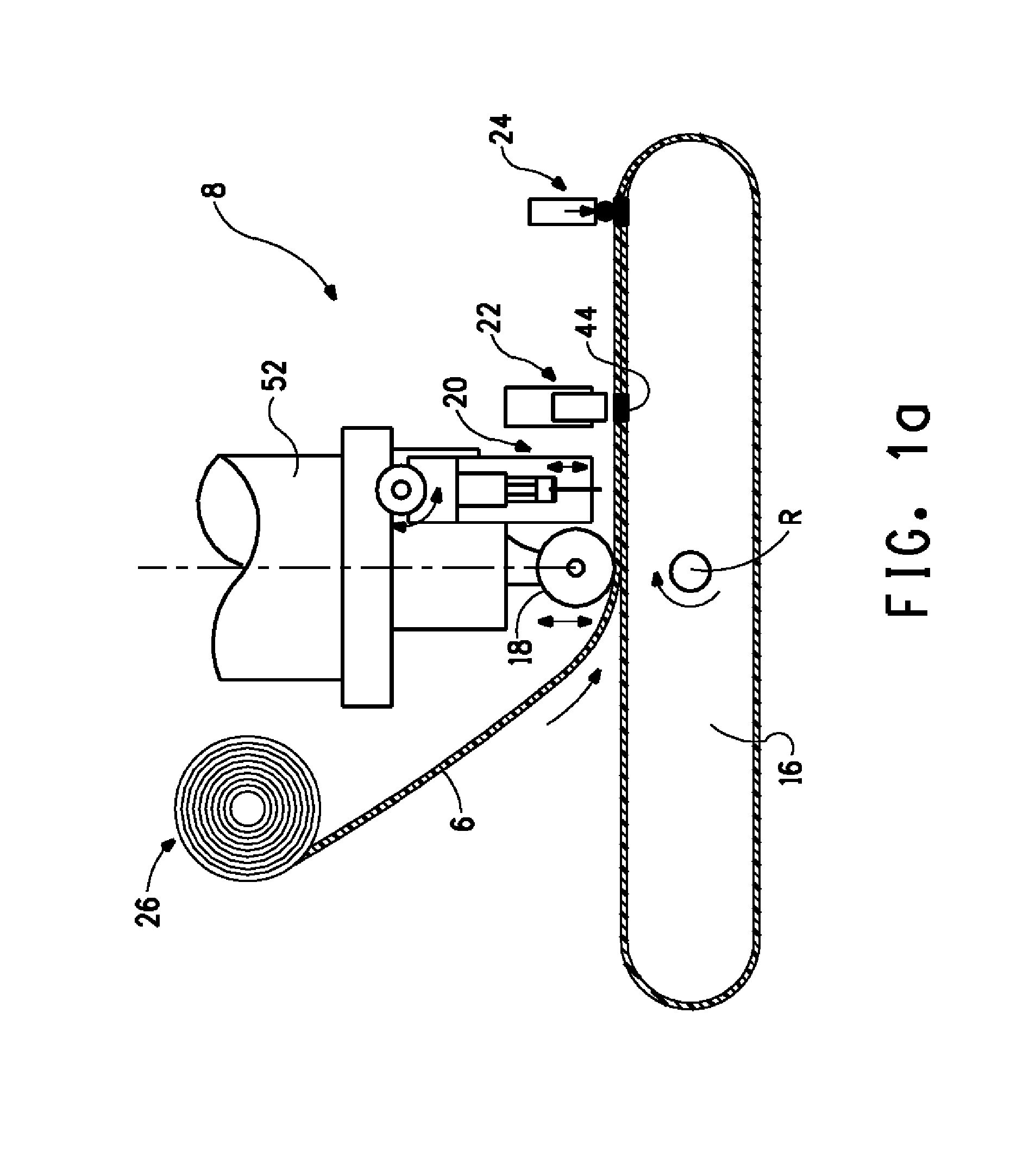
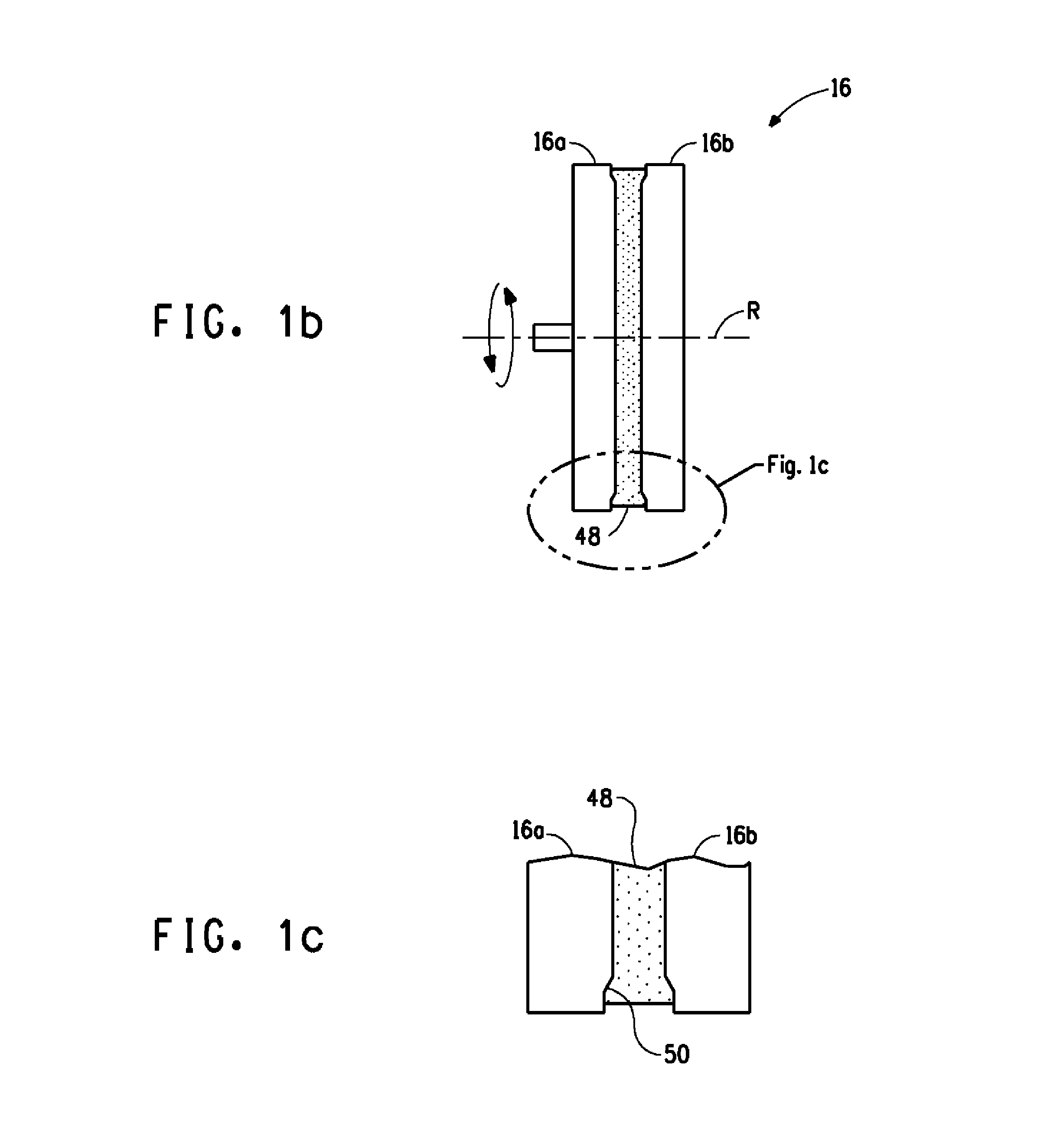
[0052]Referring to FIGS. 8a to 8c, an example of a composite article 4 is shown, the article in this example representing a vehicle suspension arm or control rod. The article comprises a consolidated fibre reinforced part 37 forming a closed loop, an overmolding 42 and optionally one or more inserts 40. The consolidated fibre reinforced part 37 is made from a wound unidirectional tape preform 38 made using a process according to embodiments of the invention that are described further on. Composite articles according to the invention may be formed uniquely from unidirectional tape, or from a unidirectional tape combined with inserts, overmolding, and other elements mounted to or around the wound UD tape preform. In the illustrated example of FIGS. 8a to 8c, the overmolding 42 may for example be an injected polymer, and the one or more inserts could be made of various materials, for example an insert made of a metal, composite material, or of a ceramic, depending on the application and the function to be accomplished. The closed loop fibre reinforcement 37 of the article provides structural strength to the article, especially against tensile forces Ft or beam bending stresses, or other stress components depending on the forces to be supported by the article and the geometry and spatial orientation of the article. In the present invention, the unidirectional fibres extend in a continuous, substantially uninterrupted manner multiple times around the closed loop to provide very high strength against tensile forces acting in the loop.
[0053]Referring now mainly to FIG. 1a, a schematic illustration of a tape winding robot 8 for winding a multilayer continuous closed loop of unidirectional fibre reinforced tape 6 is shown. The unidirectional fibre reinforced tape comprises unidirectional fibres, for instance glass fibre, carbon fibre, or other reinforcing fibres per se known in the art, embedded in a polymer resin, for instance polypropylene, polyamide, thermoplastic polyesters including polybutylene terephthalate, polyethylene terephthalate, thermoplastic elastomers, polyphenylene sulfide, and polyetherimide.
The tape may have a width in the order of magnitude of a few millimeters to a few centimeters, or even tens of centimeters, and a thickness in the order of magnitude of a tenth of a millimeter to a millimetre. The low thickness of the unidirectional tape allows the cold tape to be bent with a radius of curvature sufficiently small to be accommodated in the article to be manufactured without rupture of the tape during the winding process. For example, for 0.2 mm thick tape, minimum radiuses of curvature may be in the order of a centimeter. The term “cold ” as used herein is a temperature below the melt or fusion temperature of the polymer resin of the UD tape that does not enable the layers to bond or consolidate.
[0054]The unidirectional tape may be provided on a tape reel 26 with a total wound length substantially greater than the length of the tape to be wound in a closed loop for an article, such that a large plurality of articles may be manufactured using the unidirectional tape from a single reel.
[0055]The tape winding robot 8 comprises a jig 16 around which the UD tape 6 is wound, the jig thus defining a preform of the multi-layer wound UD tape 38 prior to consolidation, the jig 16 being rotatable about an axis R relative to the tape reel 26 and robot arm 52 carrying a roller shoe 18. In the embodiment of FIG. 1a the jig 16 may be movable in a direction parallel to the axis of rotation R in order to place the tape being wound on the jig laterally, so that the subsequent layer does not fully overlap the underlying layer (i.e. is offset with respect to the underlying layer), for example to make wide sections 6b of tape or narrow sections 6a as illustrated in FIG. 3d. Optionally, the jig may be movable relative to the tape reel 26 and robot arm 52 along further axes X, Y, Z in translation and/or in rotation R′, in order to enable positioning of the tape on the jig for complex forms, for instance as illustrated in FIG. 2c.
[0056]The positioning of the tape on the jig may be defined or assisted by a tape guide channel 48, 48′, whereby the jig may be made of two or more parts 16a, 16b in order to separate it from the tape winding preform 38 after completion of the winding process. The tape guide channel 48, 48′ may adopt a curved three-dimensional path that surrounds the jig or is on a face of the jig to determine the shape of the wound UD tape preform 38. The jig may further comprise any necessary cavities or positioning means, for example in the form of an insert holder portion 50 (see FIG. 1c), to accommodate an insert 40 and allow the tape to be wound around the insert as may be seen in FIGS. 8a and 2a.
[0057]The tape winding robot further comprises a roller shoe 18 mounted on a robot arm 52 that is relatively movable with respect to the jig 16, the roller shoe configured to roll along and press the stacked layers of tape, as it is being wound, against the jig. The application force of the roller shoe 18 against the tape may be defined by a spring or pneumatic or hydraulic pressure defining an essentially constant rolling pressure. This pressure is provided to guide the tape on the jig 16 and is not intended to provide any consolidation of the UD material, although it may be used to compress the layers proximate the position of performing a discrete weld. The tape winding robot 8 may further comprise a movable and actionable cutter 20 to cut the end of the tape, once the winding operation is completed. In typical applications, the tape may be wound continuously without being cut to form a winding with 3 to 100 or more stacked layers of tape. Within the scope of the invention, it is possible to provide a plurality of windings each with a plurality of tape layers, the windings being separated by a cut from each other. This may be useful in embodiments with wound UD tape sections in different materials or spatially offset. It is also possible to wind two or more tapes simultaneously either one on top of the other in the same guide channel or in separate channels, or in channels that bifurcate over a portion depending on the configuration of the part to be manufactured. This may include the use of 1 or more rollers 18, cutters 20, UD tape reels 26, and welding heads 22.
[0058]In the illustration of FIG. 8a, the jig 16 is configured to form a simple elongated closed loop preform, however the jig may take various shapes, for instance a tapered shape to produce the closed loop preform of FIG. 4a, or with narrower central portions to form the preform illustrated in FIG. 4b, and many other shapes as long as the minimum radius of curvature acceptable for the bending of the tape without rupture is respected.
[0059]The jig 16 may be provided with active location devices 24, 25 that may be in the form of pins or rollers that are movable, such that as the jig passes the roller shoe 18 at the position of the active location device 24, 25, the latter is moved out of the way. A plurality of active location devices 24, 25 mounted on the jig 16 and relatively movable and actionable with respect to the jig, may be provided around the jig. Top active location devices 24 may be configured to press the stacked layers of wound tape against the jig, and side active location devices may be configured to laterally position the tape layers. The lateral positioning of tape layers may optionally be varied from layer to layer such that a lateral offset of selected certain successive layers is obtained (e.g. to widen a portion 6b of the preform relative to other portions 6b as shown in FIG. 3d).
[0060]The tape winding robot according to embodiments of this invention advantageously comprises at least one tape fixing head 22, which in an advantageous embodiment comprises a welding head 22, on a robot arm separate from the jig, or on a displacement device fixed to the jig 16. The welding head is configured to be actionable at discrete predetermined tape winding positions to press against the outer layer of tape and locally weld the outer layer of tape to the layer below, optionally to weld a plurality of layers below the welder together. The welding head may perform the discrete welding operation by ultrasonic welding, or inductive welding, by electromagnetic radiation (e.g. microwave), or by conduction heating.
[0061]In a variant, the tape fixing head may comprise an adhesive depositing injector for depositing adhesive on the tape to bond the subsequent layer to the deposit layer. The adhesive may be a snap curing adhesive, optionally UV (ultraviolet light radiation) or heat activated, whereby the tape fixing head comprises a UV or heat activation unit.
[0062]In yet another variant, the tape fixing head may comprise a mechanical stapler to fix stacked layers of UD tape together by means of a staple, for instance a metallic staple.
[0063]The tape fixing means may also comprise a combination of the above fixing means.
[0064]In an advantageous variant, the tape is welded at discrete moments after each new winding layer is placed, such that the layers are fixed together at one or more discrete positions through essentially the whole stack of tape layers. The discrete welding operations can be performed at high speed because of the very local and thus rapid heating and cooling, allowing a fast winding of the cold tape.
[0065]The tape winding robot 8 may be provided with a single welding head or two or more welding heads at different positions around the jig configured to perform discrete position welds on the stacked layers of tape at different positions simultaneously, or at different times. In an advantageous variant with a single welding head, said welding head may be configured to effect discrete welds at predetermined positions around the jig, as the jig is turned relative to robot arm 52 and roller shoe 8. The placement of welds at or near inflexion points of curves, and/or at the bottom or top of curved portions of the preform may advantageously help to stabilize and maintain the shape of the preform by preventing relative slippage of tape layers between themselves. The end of the tape after the winding operation is completed may be welded and/or clamped by an additional crimping or clamping ring or other mechanical fixing element 46 around a branch of the wound UD tape preform 38, as illustrated in FIG. 3a. Within the scope of the invention, it is possible to weld only two discrete welds at minimum, a first weld at the beginning of the winding process, and a second at the end or towards the end of the winding process. Welds can also be discretely effected every few layers of winding, for instance every three our four layers, in which case the welding process (e.g. ultrasonic welding) may be configured to penetrate through a plurality of layers, or only a single layer.
[0066]In an advantageous embodiment, welding is effected on each layer, or almost every layer, in order to rigidify the preform by coupling all the layers of the stack together.
[0067]In a variant, the composite article may comprise an insert including a shaping support structure with positioning elements that function to shape, at least in part, the wound tape positioned on the jig, but that remain integrated in the article after removal from the jig. Such a shaping support structure may be made of a polymer or of stamped and formed sheet metal or composite or other low-cost components for permanent integration within the article, in order to reduce the complexity of the jig and the active location devices and/or to enable winding a complex preform shape.
[0068]Referring to FIG. 5, once the wound UD tape preform 38 has been formed, it may be removed from the jig 16, and transported by a transport system 12 with the grippers 28, alternatively transported by the jig 16 itself, to a heating station 10 configured to heat the
[0069]UD tape such that the polymer resin is softened and melted, but without degradation of the polymer, such that the UD tape may be consolidated. The UD tape preform may be heated by heating means including: forced hot air convection oven, infra-red oven, microwave oven, induction heating, and contact heating, combinations of these, or other heating means. The heated wound UD tape preform 38 is then transported to a mold press 14 comprising a compression tool for applying pressure on the heat softened UD tape to consolidate the tape layers and substantially remove any air or spaces between the layers.
[0070]In a variant, the UD tape preform 38 may be placed directly into an injection molding machine, optionally via a warming buffer that heats the preform close to but below the UD tape polymer melt temperature. The discrete local welding, in combination with additional stabilization of the over-molding material, gives a shear force between the different UD tape layers that prevents unravelling of the UD tape layers under load and is greater than the tractive or compressive or twisting forces that the part must meet in its use, such that full consolidation of the UD tape layers together prior to overmolding is not required, resulting in cost savings during manufacture.
[0071]In another variant, the UD tape preform 38 may be placed directly into an injection molding machine via a warming buffer that heats the preform at or above the UD tape polymer melt temperature. The over-molding polymer pressure consolidates the UD tape layers substantially bonding then together by melt fusion, resulting in near homogeneous properties in the UD tape. Consolidation prevents unravelling of the UD tape layers under load and creates a shear force resistance between the different UD tape layers that is greater than the tractive or compressive or twisting forces that the part must meet in its use. Consolidation also gives long term performance during creep and fatigue loadings. In a first embodiment illustrated in FIG. 6a to FIG. 6d, a lower die 30b comprises a die cavity 32b configured to receiving the wound UD tape preform 38, and an upper die comprising a relatively movable active core 34 and a compression die surface 32a configured to insert into the die cavity 32b and compress the wound UD tape preform 38 in a direction essentially orthogonal to the tape stacking direction. The active core 34 presses against a central portion of the lower die to prevent polymer resin from escaping the die cavity 32b during consolidation. The resulting consolidated fiber-reinforced part 37 may be removed from the die, after some cooling, and incorporated in an injection mold for overmolding or taken to other machining stations to perform other shaping or part forming and assembly operations.
[0072]In another embodiment illustrated in FIG. 7a to FIG. 7c, the lower die 30b comprises a die cavity 32b to receive the wound UD tape preform 38 therein, the lower die having lateral active cores 36 configured to press together the tape layers in the direction of stacking of the layers. In this case, the upper die 30a can be provided without an active core and functions to close the lower die cavity 32 during the compression effected by the lateral active cores 36. The dies may be provided with temperature regulation circuits, such as fluid cooling or heating circuits therein, in order to regulate the temperature during the mold compression process, and optionally for cooling the article prior to removal from the die.
[0073]The UD tape composite structures and overmolded UD tape composite structures described herein may be used in a wide variety of applications such as for example as components for automobiles, trucks, commercial airplanes, aerospace, rail, household appliances, computer hardware, hand held devices, recreation and sports, structural component for machines, structural components for buildings, structural components for photovoltaic or wind energy equipments or structural components for mechanical devices.
[0074]Examples of automotive applications include without limitation spare wheel wells, floor pans or floor pan sections, integrated structural covers and support brackets for compressed natural gas tanks, liquid propane gas tanks, or hydrogen tanks, seating components and seating frames, engine cover brackets, engine cradles, suspension arms and cradles, chassis reinforcement, front-end modules, steering column frames, instrument panels, door systems, body panels (such as horizontal body panels and door panels), tailgates, hardtop frame structures, convertible top frame structures, roofing structures, engine covers, housings for transmission and power delivery components, oil pans, airbag housing canisters, automotive interior impact structures, engine support brackets, cross car beams, bumper beams, pedestrian safety beams, firewalls, rear parcel shelves, cross vehicle bulkheads, pressure vessels such as refrigerant bottles and fire extinguishers and truck compressed air brake system vessels, hybrid internal combustion/electric or electric vehicle battery trays, automotive suspension wishbone and control arms, suspension stabilizer links, leaf springs, vehicle wheels, recreational vehicle and motorcycle swing arms, fenders, roofing frames, and tank flaps.
[0075]Examples of household appliances include without limitation washers, dryers, refrigerators, air conditioning and heating. Examples of recreation and sports include without limitation inline-skate components, baseball bats, hockey sticks, ski and snowboard bindings, rucksack backs and frames, and bicycle frames. Examples of structural components for machines include electrical/electronic parts such as for example housings for hand held electronic devices, computers.
LIST OF REFERENCES IN THE DRAWINGS
[0076] 2 manufacturing equipment
[0077]8 tape winding robot [0078] 16 jig [0079] 16a, 16b jig parts [0080] 48 tape guide channel [0081] 50 insert holder portion [0082] 18 roller shoe [0083] 52 arm [0084] 20 cutter [0085] 22 welder [0086] 24 top active location device—location roller [0087] 25 side active location device—location roller [0088] 26 tape reel
[0089]10 heating station
[0090]12 transport system [0091] 28 grippers
[0092]14 mold press [0093] 30 compression mold die [0094] 30a upper die [0095] 32a die cavity counterpart [0096] 34 active core [0097] 30b lower die [0098] 32b die cavity [0099] 36 lateral active cores [0100] 4 article
[0101]37 consolidated fibre reinforced part
[0102]38 wound UD tape preform [0103] 44 discrete welds [0104] 46 fixing element—clasp
[0105]40 inserts
[0106]42 overmolding [0107] 6 unidirectional tape
[0108]6a narrow (aligned) stacked layer portion [0109] 6b wide (offset) stacked layer portion