Drop zone rally point beacon

a rally point and drop zone technology, applied in the field of elf/vlf beacons, can solve the problems of large antennas and power, difficult to jam the system, and expose the intension of such sites, and achieve the effects of low near-field impedance, low interference, and high magnetic field intensities

Inactive Publication Date: 2013-06-13
BAE SYST INFORMATION & ELECTRONICS SYST INTERGRATION INC
View PDF3 Cites 36 Cited by
  • Summary
  • Abstract
  • Description
  • Claims
  • Application Information

AI Technical Summary

Benefits of technology

[0009]VLF signals are impervious to obstacles (cargo on the drop pallet, local trees, rocks, or urban structures) or multipath effects over short ranges. VLF signals can penetrate most materials including ground. The fields radiated by loop antennas have high magnetic field intensities compared to electric fields. The magnetic fields are proportional to 1 / r3 and 1 / r2. High magnetic field waves have very low near-field impedances which tend to minimize reflections from objects and partially conductive structures. The magnetic field amplitude range dependence on 1 / r3 allows a receiver to see rapid amplitude variations with distance, thereby helping to resolve bearing ambiguities with the direction finding (DF) solution by noting comparative changes in amplitude as the individual walks. For embodiments, a dipole can supplement the DF capability by resolving the bearing ambiguity of the loop antenna and, combined with the loop, identify the direction from which the transmitted signal is coming.

Problems solved by technology

Embodiments of the system are difficult to jam because intentional jamming would require proximity of the jammer to the beacon transmitter and receiver.
The jammer would require a large antenna and much power, thus exposing the intension of such sites.

Method used


Image

  • Drop zone rally point beacon
  • Drop zone rally point beacon
  • Drop zone rally point beacon

Examples


Embodiment Construction

[0025]The following detailed description provides example embodiments of the presently claimed invention with references to the accompanying drawings. The description is intended to be illustrative and not limiting the scope of the present invention. Embodiments are described in sufficient detail to enable one of ordinary skill in the art to practice the subject invention. Other embodiments may be practiced with some variations without departing from the spirit or scope of the subject invention.

[0026]Communications at frequencies much lower than VHF, UHF, and microwave (such as at the VLF band (10 kHz to 100 kHz)), propagate with minimal effects through terrain, fauna, weather, and man-made obstacles. Because the frequency is so low, propagation is limited to a few kilometers and has an inverse cubic relationship with distance. Transmitters for the beacon can be inexpensive and small.

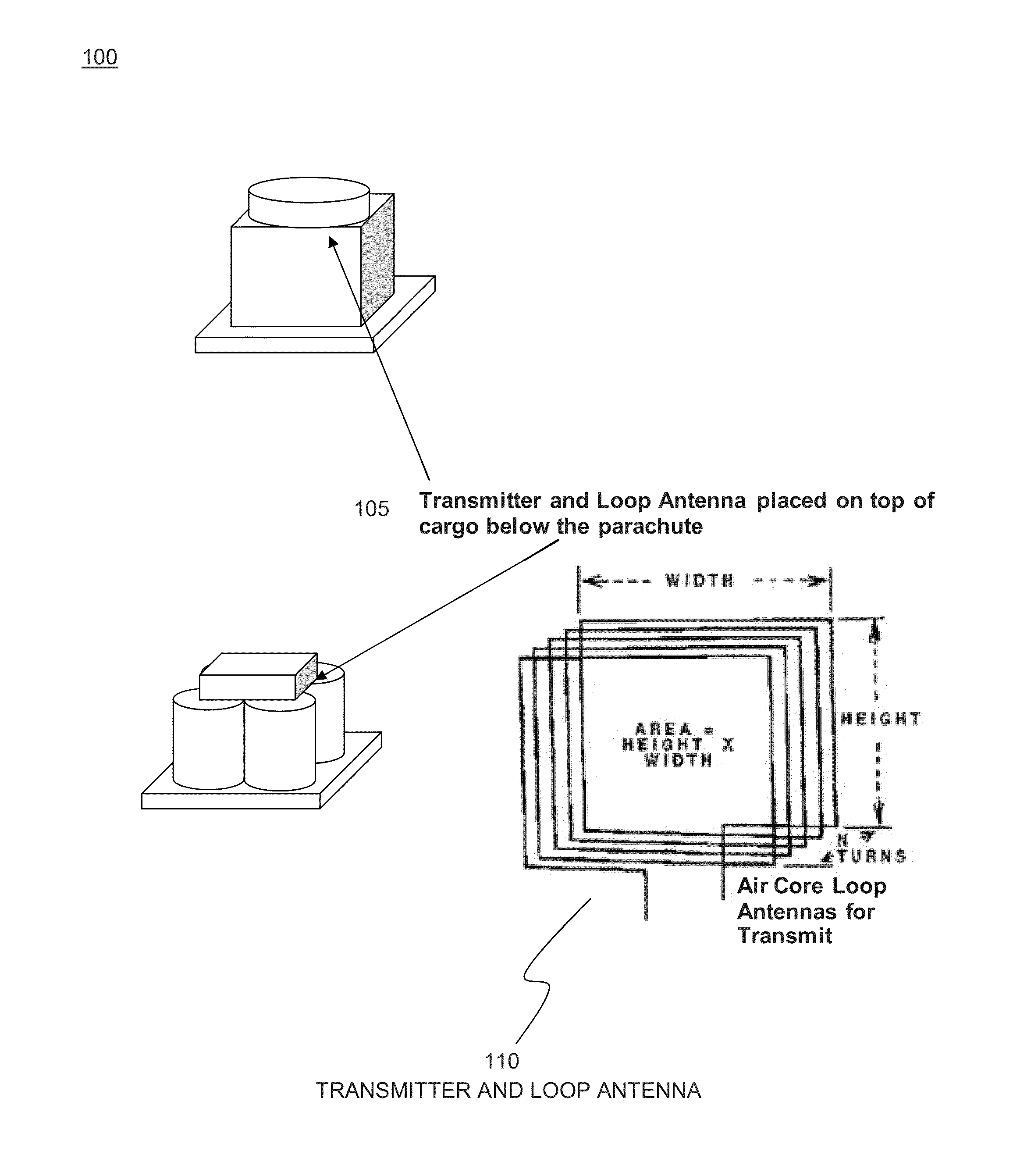
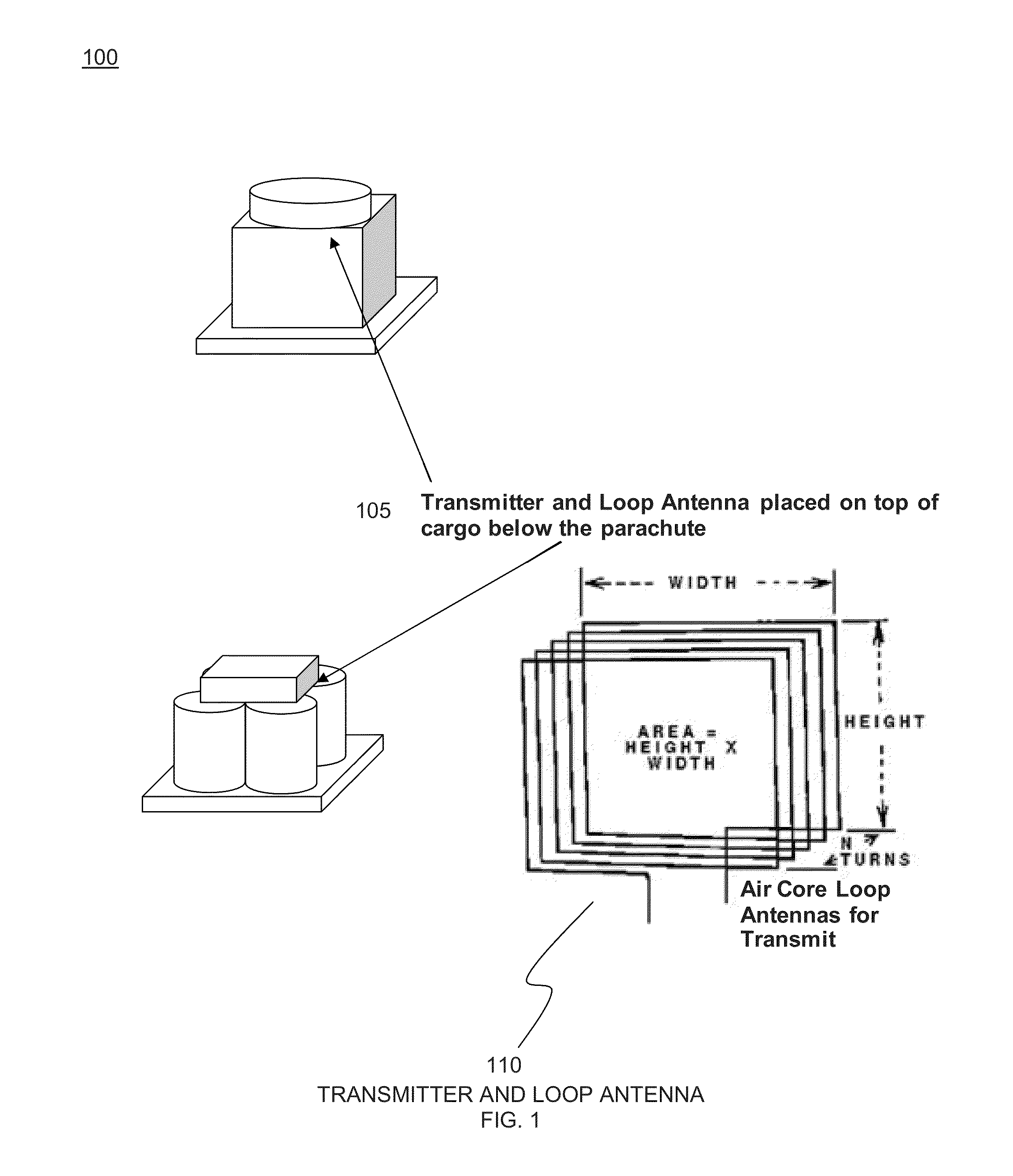
[0027]FIG. 1 depicts a transmitter and loop antenna 100 for an embodiment of the drop zone beacon sy...


PUM


Abstract

A VLF beacon operates in the near field of the antenna, providing a low impedance (magnetic) wave located by employing simple amplitude gradient and phase alignment direction finding (DF) methods. When rotated, the beacon antenna radiates its signal with little attenuation. Beacon antennas include a loop antenna which has a 1/r3 B-field amplitude relationship with distance. The antenna radiation range is limited, but the detectable near field signal is strong. The receiver comprises a simple 2-channel RF front end with filtering and an A/D converter. The antenna for each channel is a much smaller ferrite rod loaded loop.

Description

FIELD OF THE INVENTION[0001]The invention relates to an ELF / VLF beacon operating in the near field of the antenna, providing a low impedance (magnetic) wave located by employing simple amplitude gradient and phase alignment direction finding (DF) methods.BACKGROUND OF THE INVENTION[0002]Air-dropped cargo pallets do not always land in designated locations. Finding them in GPS denied environments, in darkness, in adverse weather, or on rough terrain is difficult and dangerous. An inexpensive tag or drop zone beacon identifying the cargo is needed that would radiate a signal from which the recipient could determine the proximity and direction of the pallet.[0003]Paratroopers jumping from airplanes usually convene at a designated location before beginning their mission. GPS is the preferred approach for the individual to find the “rally point.” There are areas where GPS reception is poor or unavailable such as in heavily wooded or mountainous areas or in urban areas. For this, a rally p...

Claims


Application Information

Patent Timeline
Patent Type & Authority Applications(United States)
IPC IPC(8): H04B5/00
CPCH04B5/0081
Inventor DEC, ALBERT K.ALFRED, MARIE Y.
Owner BAE SYST INFORMATION & ELECTRONICS SYST INTERGRATION INC
Why Eureka
Try Eureka