Robot, robot control apparatus, robot control method, and robot control program

Active Publication Date: 2013-06-13
PANASONIC CORP
View PDF11 Cites 26 Cited by
  • Summary
  • Abstract
  • Description
  • Claims
  • Application Information

AI Technical Summary

Benefits of technology

[0020]With the robot, the robot control apparatus, the robot control method, and the robot control program, since the impedance map variable unit is provided and u

Problems solved by technology

For example, in the case where low damping is set, though shifting is easily performed because the robots operate with a light force, the stability becomes poor.
Thus, the low damping results in the

Method used


Image

  • Robot, robot control apparatus, robot control method, and robot control program
  • Robot, robot control apparatus, robot control method, and robot control program
  • Robot, robot control apparatus, robot control method, and robot control program

Examples


first embodiment

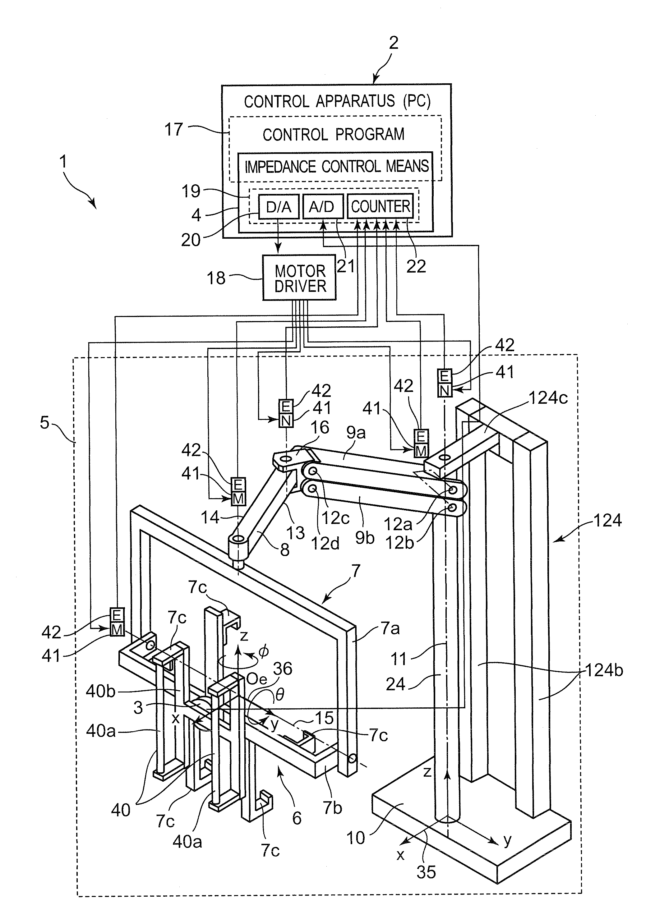
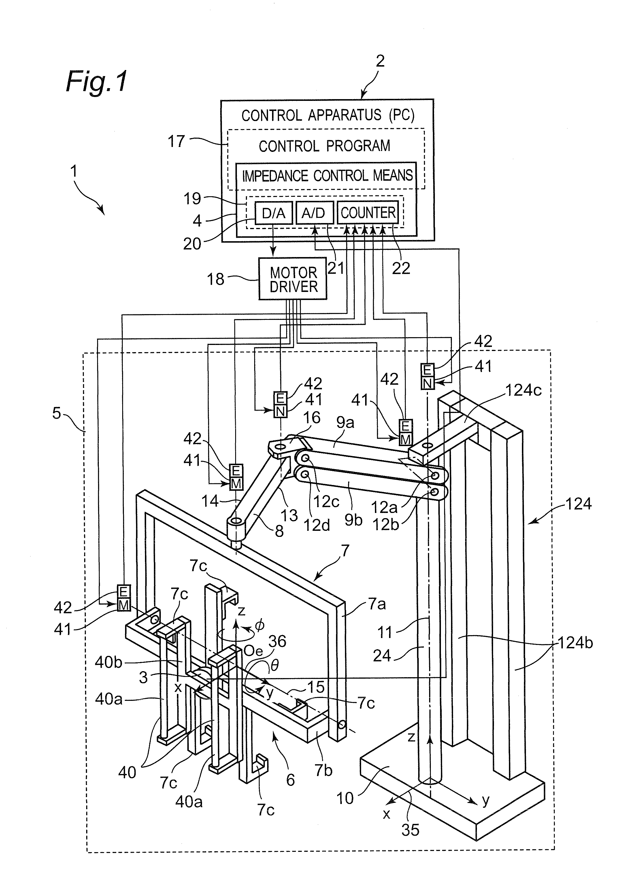
[0089]FIG. 1 shows the structure of a robot 1 according to a first embodiment of the present disclosure. The robot 1 includes a multi-joint robot arm 5, and a control apparatus 2 that controls the operation of the multi-joint robot arm 5.

[0090]The control apparatus 2 is structured by an ordinary personal computer in hardware. Further, the control apparatus 2 except for an input / output IF 19 of an impedance control means (an impedance control unit) 4 is realized in software as a control program 17 executed by the personal computer.

[0091]The input / output IF 19 is structured by a D / A board 20, an A / D board 21, and a counter board 22 each connected to an extension slot such as a PCI bus of the personal computer.

[0092]Execution of the control program 17 for controlling the operation of the multi-joint robot arm 5 of the robot 1 enables the control apparatus 2 to function.

[0093]Joint angle information which is output from an encoder 42 serving as one example of a joint angle sensor of eac...

second embodiment

[0152]The basic structure of a robot 1 according to the second embodiment of the present disclosure is identical to that according to the first embodiment shown in FIGS. 1 and 2. Therefore, the description of the common parts will not be repeated, and the difference will solely be detailed below.

[0153]In the second embodiment, as shown in FIGS. 9A and 9B, the initial state of the impedance map storage unit 48, that is, the impedance map of the reference distribution (the distribution serving as the reference before any changed or update is made, or the distribution in the initial state) of the impedance parameters M, D, and K (inertia M, damping D, and stiffness K) stored in the impedance map storage unit 48 is structured by: a first region 101 of low damping for allowing the arm end of the robot arm 5 to shift; a second region 102 of damping higher than that of the first region 101 for allowing the arm end of the robot arm 5 to be positioned; and a third region 103 of damping highe...

third embodiment

[0156]The basic structure of a robot 1 according to a third embodiment of the present disclosure is identical to that according to the first embodiment shown in FIGS. 1 and 2. Therefore, the description of the common parts will not be repeated, and the difference will solely be detailed below.

[0157]In the third embodiment, as shown in FIG. 10A, in the initial state of the impedance map storage unit 48, a second wall 54A, whose damping D is high near the stand 33 of the second workbench 32, is formed as the fourth region 104. More specifically, the initial state of the impedance map storage unit 48, that is, the impedance map of the reference distribution (the distribution serving as the reference before any changed or update is made, or the distribution in the initial state) of the impedance parameters M, D, and K (inertia M, damping D, and stiffness K) stored in the impedance map storage unit 48 has: a first region 101 of low damping for allowing the hand 6 of the robot arm 5 to sh...


PUM


Abstract

A robot includes a multi-joint robot arm, an external force acquiring unit arranged at the multi-joint robot arm to acquire an external force, and an impedance control unit that causes the multi-joint robot arm to operate as a virtual spring-mass-damper system based on the external force acquired by the external force acquiring unit. The impedance control unit has an impedance map storage unit that defines impedance parameters at each of points of the work region, and an impedance map variable unit that changes the distribution of the impedance parameters in the impedance map storage unit in accordance with the current arm end position or the current arm end velocity of the multi-joint robot arm.

Description

CROSS-REFERENCE TO RELATED APPLICATIONS[0001]This is a continuation application of International Application No. PCT / JP2012 / 001824, with an international filing date of Mar. 15, 2012, which claims priority of Japanese Patent Application No. 2011-058629 filed on Mar. 17, 2011, the content of which is incorporated herein by reference.DESCRIPTION OF THE RELATED ART[0002]The technical field relates to a robot cooperating with a human, such as a robot provided with a robot arm to assist in works including power assist at factorys, homes, nursing care sites, and the like, a control apparatus of the robot, a controlling method of the robot, and a control program of the robot.[0003]In recent years, human cooperative robots, which performs work assist such as power assist by operating in cooperation with humans in factories or the like, are drawing attention. Since such human cooperative robots operate as being manipulated by humans, practical works can be done without a high autonomous func...

Claims


Application Information

Patent Timeline
IPC IPC(8): B25J9/16
CPCB25J13/085B25J9/16G05B2219/39346G05B2219/36429G05B2219/39342B25J9/1633
Inventor OKAZAKI, YASUNAO
Owner PANASONIC CORP
Why Eureka
Try Eureka